
Related Manuals for biodex SYSTEM 4


Summary of Contents for biodex SYSTEM 4
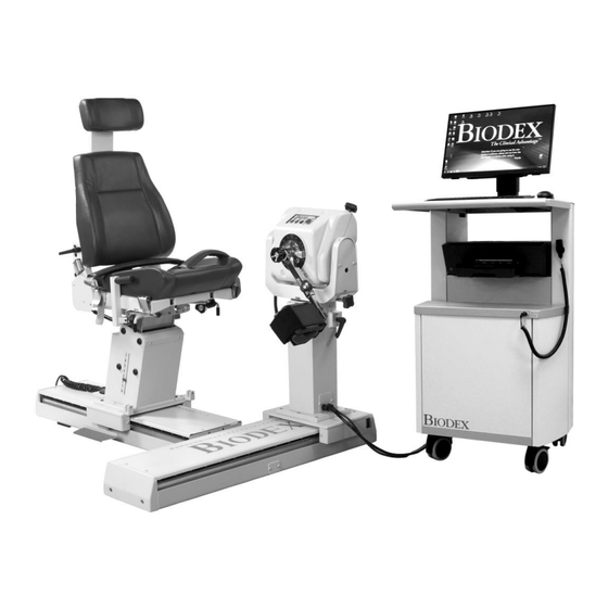
- Page 1 SYSTEM 4 (Advantage BX Software 5.2X) INSTRUCTIONS FOR USE 850-000 840-000 852-000 FN: 20-001-CLR Rev A...
-
Page 2: Contact Information
Additional information and resources, including installation instructions, are available upon request or directly from the Biodex website, http://www.biodex.com. If the desired information is not found, please feel free to contact a local distributor or Biodex directly at supportservices@biodex.com Thank you, Biodex Medical Systems, Inc. -
Page 3: Table Of Contents
Getting Started ........................31 Home Screen .......................... 32 Connection Status ......................... 33 Introduction: New Software ....................33 Tips for Using Biodex Advantage BX™ Software ..............33 Protocol Based Activity ......................34 Defining ROM ......................... 40 Protocol Based Activity Screen ....................42 Practice Reps with Activity .................... - Page 4 Patient Management ......................72 Protocol Management ......................73 Data Management ......................... 77 Application Settings ......................86 System Settings ........................94 Facility Info and Logo ......................98 Normative Data ........................99 4. Clinical Education ........................100 5. Software Updates ........................100 6.
-
Page 5: Definition Of Symbols
Definition of Symbols The following symbols and their associated definitions are used and implied throughout this manual. -
Page 6: Product Certifications And Classifications
NOTE: Component part lists, descriptions, calibration instructions, or other information used to assist service personnel to repair those parts of the equipment that are designated as repairable for this product are provided on the Biodex website, www.biodex.com or can be obtained by contacting Biodex Customer Service (see Contact information). -
Page 7: Warnings And Cautions
It may also help to have a fixed location from which all subjects approach and leave the chair. Be aware that use of Biodex technology requires professional expertise for discerning appropriate treatment techniques. Each subject’s unique situation should be taken into account before beginning any type of testing or rehabilitation program. -
Page 8: Warranty
CAUTION: The system is intended to remain in one location during operation. To relocate the system, the system is disconnected from power source. Use the wheels to move the system. Warranty Refer to the warranty card included with the product or contact Biodex Support Services. -
Page 9: Important Safety Information
Important Safety Information Considerations for Safe Operation of the System 4: 1. The clinician should always be present during testing or activity sessions. Do not allow subjects to test or exercise by themselves. 2. Range limits should always be set after the subject is positioned according to protocol and before switching to a test or activity mode. -
Page 10: Introduction
1. Introduction Indications for Use The System 4 is used to identify, treat, and document the physical impairments that cause functional limitations typical of sports injuries, orthopedics, pediatric medicine, and neurorehabilitation. Contraindications Absolute Contraindications Acute strain (musculotendinous unit) or sprain (non-contractile tissue) ... -
Page 11: Getting Started
2. Getting Started Controls and Adjustments 1. Tilt Knob (locking) 2. Tilt Scale 3. Tilt Key 4. Locking Knob Storage 5. Rotation Knob (locking) 6. Position Color Code Label 7. Foot Pedals (travel) 850-000, 840-000 (not depicted) 8. Height Lever 9. - Page 12 Dynamometer Tilt: Permits rotation of the dynamometer on a vertical plane allowing the shaft axis to tilt upward or downward from the horizontal position. To tilt the dynamometer, support the dynamometer with one hand. With the other hand, loosen the Tilt Knob in a counterclockwise direction. Gently push or pull the dynamometer to the desired position.
- Page 13 Hold/Resume: Stops shaft rotation. Press this button a second time to resume the test or activity session. One Hold/Resume button is located atop the dynamometer next to the Comfort Stop. A second Hold/Resume button is activated by a hand-held remote located to the right of the control panel on the Clinical Data Station (CDS) cart.
- Page 14 CAUTION: Comfort Stops (Dynamometer, Remote): These buttons provide the subject with the ability to instantaneously terminate exercise in any mode. Depressing either the large red button atop the dynamometer or the hand-held remote button causes immediate cessation of dynamometer shaft rotation. The purpose of this control is to guard against moving the subject into a portion of the range of motion that, for any reason, is contraindicated.
-
Page 15: Positioning Chair
Positioning Chair 1. Seat Rotation Handle 2. Receiving Tubes 3. Chair Foot Pedals 4. Seat Height Foot Switches 5. Cervical Support Adjustment Knob 6. Seat Back Tilt Handle 7. Seat Back Fore/Aft Handle 8. Stabilization Handles Figure 2.2. Positioning Chair Adjustments (850-000). Seat Rotation The positioning chair offers 360 degrees of rotation in the horizontal plane with détente... - Page 16 Seat Back Tilt: This adjustment allows the user to select any of five seat back angle settings: 85, 70, 55, 40 and 25 degrees. To adjust the seat back tilt, pull up on one of the Seat Back Tilt Handles, located on either side of the lower seat back frame.
-
Page 17: Seat Back Brace
Back Brace with the clevis on the seat back and insert the clevis pin. 3. Release the Seat Back Handle and lower the seat back to “10” on the seat back tilt scale. Figure 2.4. Attaching the Seat Back Brace to the System 4 Seat Back Clevis. -
Page 18: The Controller
Figure 2.5. Attaching the Seatback Brace to the System 4 Trolley Mount Clevis. 6. To rotate the seat to the opposite 0- degree position, disconnect the lower end of the back only. -
Page 19: Readying The System For Use
Service Representative whenever the status panel indicates a malfunction. Figure 2.8. Rear Panel Figure 2.9. Front Panel Figures 2.8 and 2.9. The System 4 Controller front panel (right) and rear of unit (left): 1. Main Power Switch 2. Dynamometer Power Switch 3. -
Page 20: Dynamometer Attachments
NOTE: Should a coded initialization error message be displayed, contact Biodex Customer Service at 1-631-924-9000 and Press 3 for Service. Dynamometer Attachments CAUTION: Shaft Red Dot (dynamometer shaft): The small red dot on the end of the dynamometer shaft provides an index for proper alignment of attachments on the dynamometer setup. - Page 21 Figure 2.9. Hip Attachments (Left and Right) Patterns: Hip: Extension/Flexion, Abduction/Adduction Shoulder/Elbow Adapter Shoulder Attachment Figure 2.10. Shoulder Attachment (Insert in Shoulder/Elbow Adapter) Patterns: Shoulder: Extension/Flexion, Abduction/Adduction Diagonals Figure 2.11. Shoulder/Elbow Attachment (Insert in Shoulder/Elbow Adapter) Patterns: Shoulder: Internal/External Rotation Elbow: Extension/Flexion (remove cuff), NOTE:...
- Page 22 Wrist Wrist Adapter Attachment Figure 2.12. Wrist Attachment Patterns: Wrist: Extension/Flexion Radial/Ulnar Deviation Forearm: Pronation/Supination...
-
Page 23: Using The Combination Ankle Attachment
Using the Combination Ankle Attachment Figure 2.13. The Combination Ankle Attachment Adjustment Mechanisms. Footplate Rotation Lever Footplate Tilt Lever Heel Cup Release Buttons Footplate Adapter Locking Knob Ankle Attachment Adapter Toe Strap Ankle Strap... -
Page 24: Adjusting The Footplate
The Combination Ankle Attachment (#830-331) is color-coded to facilitate set ups for all ankle patterns. To prepare the attachment for use, line up the appropriate color coded position tags for footplate tilt and rotation with the red dots on the attachment shaft and Footplate Rotation Lever. -
Page 25: Shutting Down The System At The End Of The Day
Shutting Down the System at the End of the Day At the end of the day: 1. Close the Advantage BX Software application by selecting the Power icon at the top right corner of the screen. The following choices display: Shut Down PC, Restart, PC, and Exit to Desktop. -
Page 26: Modes Of Operation
Modes of Operation The System 4 offers several modes of operation. Isokinetic Mode – In this mode, the dynamometer acts to control velocity, allowing the subject to accelerate up to, but no higher than, the maximum speed value selected for each direction of shaft rotation (accommodating resistance). - Page 27 The Passive Mode – The Passive mode allows the dynamometer to provide continuous motion at constant velocity, with direction changes occurring only when range of motion limits are reached. In Passive mode, the dynamometer initiates motion when the <Start> button is pressed, requiring no active participation by the subject.
- Page 28 Isometric Mode – In this mode, the dynamometer maintains zero velocity at any selected point in the range of motion. Significant change in joint angle and overall muscle length does not occur. Isometric Mode Clinical Applications: 1. The Isometric mode may be used pre- or post-surgery with discretion. 2.
-
Page 29: Additional Considerations
2. Electrical stimulation may be used in conjunction with any of the tests or activity modes on the System 4. 3. Consider ending a rehabilitation set by work or time, especially if the goal is to improve endurance. -
Page 30: Proper Testing Technique
Set Up and Positioning Videos Instructional videos on setting up and positioning for the System 4 can be viewed at any time on your phone, computer, or other devices. These videos will be updated continuously so you will not need to wait for a software upgrade to see the latest videos: https://www.biodex.com/videos/mjs-setup... -
Page 31: Software Operation
NOTE: Ensure the dynamometer is free of attachments, otherwise an error will display. 2. After the boot, it will launch the application software automatically (you can also double- tap the Biodex System 4 shortcut). The screen below displays. NOTE: The screen below will only display when the dynamometer is freshly powered on. -
Page 32: Home Screen
NOTE: The data in this Instructions for Use (IFU) manual may not represent real-world situations and the screens may not show the most current version of the software. Home Screen From the S4 Home screen, you can: Start a Protocol Based Activity ... -
Page 33: Connection Status
Introduction: New Software You may be familiar with using Advantage Software 4.X on the System 4. The following are some tips for how to use the new software, and the differences between the Biodex Advantage BX 5.X and Advantage 4.X Software. -
Page 34: Protocol Based Activity
10. If a Bilateral Activity (test) is selected via repeating an activity, and only the involved side is desired, use the skip button to skip the uninvolved side. 11. Reports: Report by date or Report by patient Note: Make a selection to Select a report type. a) Report by Date: Bottom Left Report by Patient: Top right 12. - Page 35 Click the Protocol Based Activity icon and four options will appear: New Activity: Quick Start, New Activity: Add New Patient, New Activity: Existing Patient, and Repeat Activity: Existing Patient. New Activity: Quick Start To start an activity without having to enter patient information at the beginning, select the New Activity: Quick Start option.
- Page 36 5. Select the Mode: Isokinetic, Isometric, Isotonic, Passive, Reactive Eccentric. 6. The list of available protocols will display (both built-in and custom) including built-in protocols for the ACLR-RTP tests and report. Select a protocol from the list. NOTE: If no protocol is available, a protocol can be added by clicking the button (see image below).
- Page 37 NOTE: When a protocol is selected it displays information under “Details”. Click the [+] to view more information about that protocol. 7. Select the Next icon. The ROM (Range of Motion) Setup screen displays. NOTE: Please see the Defining the ROM section for the next set of instructions. NOTE: To add/pin the activity to the Frequent Activity list, select the Save Activity icon.
- Page 38 New Activity: Add New Patient If a patient does not exist in the system yet, the information can be added quickly using the New Activity: Add New Patient option. 1. Select the New Activity: Add New Patient icon. The Add Patient screen displays. 2.
- Page 39 New Activity: Existing Patient Once a patient already exists, select that patient from the list: 1. Select the New Activity: Existing Patient icon. The Select Patient screen displays. 2. Select an existing patient from the list. Use the up and down arrows to look through the list, if necessary.
-
Page 40: Defining Rom
Defining ROM 1. On the ROM (Range of Motion) Setup screen, select the Involved Side. 2. Select the Side for the ROM. NOTE: The Set Limb Weight option is defaulted to ON. - Page 41 3. Position the dynamometer attachment to the Towards position and select the Toward icon to record the position. Arrows will display at the selected Toward limit. 4. Position the dynamometer attachment to the Away position and select the Away button to record the position.
-
Page 42: Protocol Based Activity Screen
Protocol Based Activity Screen Once the ROM has been defined and the Next icon is selected, the Protocol Based Activity screen displays. Depending on the settings chosen for Practice (from Utilities on the Home Screen), either a Practice Trial button will appear or a mandatory Practice Trial will be included at the beginning of the activity before each set. - Page 43 4. Once the activity has started: a. A graph will be displayed. b. Metric of Peak Tq, Total Work and %CV will be displayed on the bottom of the graph. c. Applied Torque displays the direction of the dyna shaft movement. d.
- Page 44 NOTE: The current set will be highlighted in white with blue text. Once a set has been completed, it will turn to green text. NOTE: When the Previous Set icon is clicked, a message will display asking whether you want to overwrite the previous set. You can either proceed or cancel the action. 6.
- Page 45 NOTE: If the patient is unable to complete a set, select the Stop icon. This will abort that particular set and will record as DNC (did not complete). The cancelled set will be displayed in red at the bottom. Click Start to begin the next set. 7.
-
Page 46: Practice Reps With Activity
Practice Reps with Activity There are two ways to perform practice reps with Activity: performing practice reps as needed or including practice reps before each set. Option A: Perform Practice Reps as Needed (Default Setting) 1. Navigate to Utilities>Application Settings>General Settings. NOTE: You may be asked for your Access Code after selecting Application Settings. - Page 47 Option B: Include Practice Reps before Each Set 1. Navigate to Utilities>Application Settings>General Settings. NOTE: You may be asked for your Access Code after selecting Application Settings. 2. Ensure that the following two settings are highlighted/selected: Auto Start After Rest Period – If this is selected, you will lose the chance to have a Practice Trial on your next session.
- Page 48 5. Select the Start icon to begin the Practice Trial. NOTE: There are an unlimited amount of practice reps. Practice Trials will have the same properties (speed, torque, etc.) as the activity. Practice Trial results are not recorded. 6. To start the actual Activity Session, click the Stop icon. Alternatively, you can let go of the attachment, letting it fall back to the Start position.
-
Page 49: Activity Results
Activity Results IMPORTANT NOTE: If the “Test Completion Screen Time Out” setting is chosen (Utilities>System Configuration> Display Settings), after the set amount of time expires on the Activity Results screen, you will be returned to the Main Menu in 30 seconds whether or not the results have been saved. The Save icon must be clicked in order for your work to be saved. - Page 50 3. Select the Save icon if you wish to save the results. Use the left and right arrow buttons to view additional report pages. NOTE: Data are not saved until the Save icon is clicked. 4. The Activity Results screen allows you to change the settings of the results. Options like Window Data (for ISOK only), apply Filter, change the view of the graph to Position based or Time based graph, selection of Best Work, Peak Torque (for Position based graph), selection of Torque, Velocity and Position (for Time based graph) can be used.
- Page 51 6. Select the Report Settings icon to change your Report Settings or to Print the report directly from this page. NOTE: The same post-processing filter can be applied before printing the report.
-
Page 52: Training Setup
Training Setup To start a new Training session: 1. Click the Training icon. The Training Setup screen displays. NOTE: Use the Home icon at the top of the screen at any time to return to the Home screen. NOTE: Select the Back button to return to the previous screen. 2. - Page 53 4. Select a mode. 5. Select a side: Left, Right, or None. 6. Position the dynamometer attachment to the Toward position and select the Toward button to record the position. Arrows will display at the selected Toward limit. 7. Position the dynamometer attachment to the Away position and select the Away button to record the position.
-
Page 54: Training
Training 1. The Training screen will display: a. A Graph option in the middle. b. The bottom portion will display different control options (Speed, Torque, %ROM etc.). NOTE: Speed, Torque, and %ROM Limits can be adjusted after a session has started. - Page 55 NOTE: The settings icon gives additional options during a Training session, including Graph Display, Grid, X-Axis Options, and Y-Axis Options. 2. Choose Control Options from the Training screen before starting a session. 3. Control options can be changed during the session (after starting the session) but the End by Option is not allowed.
-
Page 56: Reports
Reports To access reports: 1. Select the Reports icon. Two Options are displayed. 2. Select the Report by Date or the Report by Patient icon. Report by Date The Report by Date screen displays the list of activities within the date range defined. This option allows access to individual reports, not progress reports. - Page 57 3. Select an activity. 4. Select a report type on the bottom left: Summary Report or Comprehensive Report. The Report icon on the bottom right will become visible.
- Page 58 NOTE: You may select the Settings icon to change the Report Settings. Any settings applied to the report will not change the original data. The settings are applied to display post-processed data. 5. Select the Report icon. The Report Viewer screen displays. 6.
- Page 59 Report by Patient Use the Report by Patient option to access a report for an individual patient. 1. Select the Report by Patient icon. The Report Selection – by Patient screen displays. 2. Select a patient. NOTE: You may also search by typing the patient’s name into the Name field or the patient’s ID into the ID field.
- Page 60 6. Select the Report icon. The report will load and the Report Viewer screen will display. 8. Select the Print icon to print the report or the Save PDF icon to save the report. 9. Continue to follow the prompts. If Left or Right was chosen as the involved side during the ROM setup, you will select either Involved or Uninvolved.
-
Page 61: Return To Play
Biodex Isokinetic strength test scores are considered essential objective criteria along with functional, agility, and psychological readiness testing in the return to play decision. The Biodex Isometric test report and Isometric testing is typically used in the early phases of ACL rehabilitation. - Page 62 Test Results Symmetry: If the goal of each leg’s Average Peak Torque or Total Work is achieved > 90% a Green will be noted by the result. If symmetry is below the goal, a red will be noted. The other Isokinetic strength measurements are compared to protocol, gender and age specific goals.
- Page 63 ACLR-RTP Isometric and Isokinetic Report Protocols and Goals Isometric Built-in Protocols Goals Quadriceps: Avg PT ftlb: Symmetry ratio > 90% Angle: 60 degrees PT/BW % Quads: Direction: Away and Towards Age 15-25 Male 100% Female 90% decrease 10% per decade* Contraction time: 10 seconds Hamstrings: Relaxation Time: 10 seconds...
- Page 64 Return to Play Test This section discusses the three ways to complete a Return to Play Test. NOTE: The first method is recommended because it utilizes the built-in RTP Protocols, which come with goals. To complete a Return to Play Test using one of the built-in RTP Protocols: 1.
- Page 65 If you prefer to create your own RTP Protocol rather than using one of the built-in RTP Protocols: 1. On the Home screen, select Utilities. 2. Select Protocol Management. 3. Select the Add icon (must be Knee, Bilateral, and either Isokinetic or Isometric). 4.
- Page 66 To create your own RTP Protocol with a new patient: 1. Click Protocol Based Activity on the Home screen. 2. Select New Activity: New Patient. 3. Enter all necessary New Patient information and click the Next icon. 4. Select Knee for the Joint. 5.
- Page 67 Return to Play Report The Return to Play report can be accessed through the Reports option or the Activity Results screen. Reports 1. Select Reports on the Home screen. 2. Select Report by Patient (preferred method) or Report by Date. 3.
- Page 68 Activity Results 1. On the Home screen, click Utilities. 2. Select Patient Management. 3. Select a patient. 4. Select an Activity. 5. On the Activity Results screen, select Return to Play as the report type under Options for Report Settings. 6.
- Page 69 Isokinetic ACLR Return to Play Report NOTE: The data shown is for demonstration purposes only and does not reflect the actual age of the patient.
- Page 70 Isometric ACLR Return to Play Report NOTE: The data shown is for demonstration purposes only and does not reflect the actual age of the patient.
-
Page 71: Dynamometer Status
Dynamometer Status A Communication Error message will display if the dynamometer has been disconnected from the software. Reconnect the computer cable from the dynamometer to the PC, and select the Resume icon to recover. NOTE: You may need to restart the PC after the cable has been reconnected. If the Resume icon does not recover the system, perform a full power cycle: 1. -
Page 72: Utilities
Utilities Accessing the Utilities options may require an access code to be entered. The default access code is 159. We recommend changing it. NOTE: The access code is always enabled for the Utilities, Protocol Management, Patient Management, Application Settings, and Data Management. This cannot be disabled. You can change the access code in the System Settings, and enable an access code for entering the application. -
Page 73: Protocol Management
4. Select the Next icon. NOTE: The patient must have one or more activities for the Next icon to appear. 5. Select an activity from the Stored Activity List screen. If the Next button is clicked from the search result of Patient Management screen, it will display only the activities of that Joint type. - Page 74 NOTE: Custom protocols are marked with an asterisk (*). Built-in protocols cannot be edited/deleted. NOTE: The properties of a protocol cannot be changed because it would affect the results. If a protocol is already being used, save it under a new name to change it. Protocols that have been used are marked with three dots.
- Page 75 Add Protocol 1. On the Protocol Management screen, click the Add icon. 2. Select the Joint, corresponding Pattern, Type, Mode, and Contractions. 3. Enter a value for Number of Sets. This will create columns for Sets. 4. Choose the End By option – Reps, Work, Time. 5.
- Page 76 2. On the next screen it will display the details of the Protocol. NOTE: If a protocol is built-in or has already been used for a saved activity result, you will not be allowed to edit that protocol. 3. If the protocol is not used yet, and not a factory protocol, any properties of the protocol can be changed.
-
Page 77: Data Management
Data Management Data Management can be accessed through the Utilities option on the Home screen. Exporting The Exporting functionality and various export formats available will be explained in this section. Multiple Data Export can be accessed through Data Management, while Single File Export can only be accessed from the Activity Results screen. - Page 78 9. Click the Data tab. 10. Select the From Text icon. 11. Run through the Text Import Wizard, clicking the “Delimited” radio button and clicking the Next button. NOTE: The images below are based on Microsoft Office 2010. Other versions may have the settings under a different menu.
- Page 79 Multiple Data Export To export data: 1. Select Utilities on the Home screen. 2. Select Data Management. 3. Click Export Activity Data. 4. Your search can be filtered by using the Name/ID, Joint, Type, Mode, and Time Frame fields. 5. Ensure the file location is correct.
- Page 80 6. For Export File Format, select from the following file types: .txt – Includes all metrics from the Comprehensive Report. Can be imported to Excel or other applications for normative data or any other usage. Data can be exported as either Bilateral or Unilateral (it cannot be combined).
- Page 81 .xml – The most detailed format, it shows all of the information from a Comprehensive Report, and additional metrics including: • Patient Information • Test Parameters • Set Information • Rep Information • Data Points 7. Select the Export icon. NOTE: Export Activity Data operation may take time depending on how much data is selected to export.
- Page 82 Importing To import a file: 1. Click Utilities on the Home screen. 2. Select Data Management. 3. Select Import Activity Data. 4. Specify the File Location. 5. Select the file. A pop up message will appear that says, “Selected file data will be imported and merged with existing data”...
- Page 83 Deleting To delete multiple files: 1. Navigate to the Home screen and select the Utilities option. 2. Select Data Management. 3. Select Delete Activity Data. 4. The Name/ID, Joint, Type, Mode, and Time Frame fields can be used to filter the search. 5.
- Page 84 Backup Database The backup database will back up the unit’s database and the changes made to the settings of that unit. It is not a data export option. 1. Enter the Access Code 159 and select the OK icon. 2. Select Backup Database. 3.
- Page 85 Restore Database The Restore Database option will restore the unit to the previously backed up data and the changes made on settings. 1. Enter the Access Code 159 and select the OK icon. 2. Select Restore Database. 3. Select the folder icon. A pop-up for location selection displays. 4.
-
Page 86: Application Settings
Application Settings The Application Settings option allows settings to be changed. Any changes made to this screen, will be saved. NOTE: When the Reset to Default icon is selected, it will only reset the section the user is currently on. 1. - Page 87 Torque at – Used on report settings for Comprehensive report type for a specific position. The default setting is 30 deg(s). Torque in – Used on report settings for Comprehensive report type for a specific amount of time. The default setting is 0.18 sec(s). NOTE: Refer to the torque descriptions on page 27 of the manual for further information.
- Page 88 Dynamometer Settings We recommend keeping the default settings on the device. Properties can be changed if needed. Set the Isokinetic Window Threshold – The subject is allowed to accelerate up to, but no higher than, a maximum speed value (default is 70%). ...
- Page 89 Once the settings are made, the Analog Signal Settings will be permanently set in the System 4 even if the unit is completely shut down and restarted. The current settings can always be verified by running the utility – it will show the current active settings.
- Page 90 Analog Signal Resolution Affected by Scale Factor The analog signals range from –5 volts to +5 volts, resulting in a total range of 10 volts. With the standard Remote Access option available, all analog output signals are at full scale (full scale being the default). Full scale for torque as an example is –512 ft-lb to +512 ft-lb (-696 to +696 Nm), for a total range of 1024 ft-lb (1392 Nm).
- Page 91 Check with a particular interface device manufacturer. If not, make a cable to communicate if the other device’s connections are known. The connection is labeled REMOTE ACCESS on the back of the Biodex CDS cart. It is a DB- 15 female connector.
- Page 92 Remote Access Connection – DB-15 Female Connector...
- Page 93 BNC Cable Example...
-
Page 94: System Settings
To adjust the Analog Signal Settings: 1. Select Utilities on the Home screen. 2. Select System Settings and then Analog Signal Settings. 3. Set the Velocity Scaling, Torque Scaling, Position Scaling, Output Frequency, and/or Output Mode. 4. Select the Back or Home icon to return to a previous screen. System Settings Any changes made to the System Settings on this screen will be saved. - Page 95 Display Settings To adjust the Display Settings: 1. Select Utilities on the Home screen. 2. Select System Settings. 3. Select Display Settings. The following display settings can be changed: Test Completion Screen Time Out – Set the time between off to 30 minutes. If enabled, when set time expires on the Activity Result screen, the user will be returned to Main Menu in 30 seconds whether or not the results are saved.
- Page 96 Regional Settings To adjust the Regional Settings: 1. Select Utilities on the Home screen. 2. Select System Settings. 3. Select Regional Settings. The following properties of the System (PC) can be changed: Regional Format – Regional settings can be selected from the dropdown. ...
- Page 97 Security Settings To adjust the Security Settings: 1. Select Utilities on the Home screen. 2. Select System Settings. 3. Select Security Settings. The following settings can be adjusted: The Access Code can be required or not required at Startup. ...
-
Page 98: Facility Info And Logo
Facility Info and Logo To change the Facility Info and Logo: 1. Select Utilities on the Home screen. 2. Select System Settings. 3. Select Facility Info and Logo. The following settings can be adjusted: Add the Facility name, address, phone/web/email information into the text boxes. -
Page 99: Normative Data
From the Normative Data screen you can: View a set of Normative Data. Edit Normative Data. Narrow down the Normative Data using the Search function or up and down arrows. NOTE: For further information, visit the System 4 Clinical Resources page: https://www.biodex.com/physical-medicine/products/dynamometers/system-4- pro/clinical-resource-manual... -
Page 100: Clinical Education
Manuals tab at: www.biodex.com/s4. Clinical Guidelines, webinars, and research documents are available at www.biodex.com and the Biodex YouTube channel offers instructional videos. Support staff is also available to assist with clinical and mechanical questions and problems. It is important to spend time practicing on the Dynamometer. Practice helps to improve the clinician’s skill level and effectiveness with patients’... -
Page 101: Maintenance
6. Maintenance Cleaning Instructions With the system turned OFF, wipe down all surfaces with a damp cloth. Mild soap and water can be used to remove stains and scuff marks. Pay particular attention to the upholstery that can be damaged by exposure to perspiration and other body fluids. NOTE: DO NOT use cleaning solutions containing ammonia or alcohol to clean upholstery. -
Page 102: Disposal
NOTE: The attachment will not be released and will not proceed to the next step when weight is detected. NOTE: Additional information can be found at: www.biodex.com/s4 Disposal An appropriate waste disposal company is to be contacted (i.e., the local collection point for waste separation). -
Page 103: Data Interpretation Guide
7. Data Interpretation Guide Definition of Terms PEAK TORQUE (TQ) (ft-lb): Highest force output during a repetition. Indicative of a muscle's strength capabilities. AVG. PEAK TQ (ft-lb): The averages peak torque at each repetition. Represents the average force output of a given set. PEAK TQ/BW (%): Highest force output normalized to bodyweight. - Page 104 TORQUE (ft-lb): A function of force and distance from the axis of rotation as measured by the Biodex dynamometer. GOAL: Unilateral comparison of peak torque to body weight ratio to literature published on specific joints and pathologies.
-
Page 105: Curve Analysis
Curve Analysis Characteristics of Pathologies (Davies 1992) -
Page 106: Specifications And Certifications
8. Specifications and Certifications Clinical Data Station: PC with Windows 10 Enterprise LTSC Biodex Advantage BX™ Software 22” flat panel touchscreen with integrated speakers Attachments for Ankle, Knee, Shoulder, Elbow, Wrist and Hip (850-000) Calibration Kit Operating space: 64 square feet (6 square meters) (850-000, 852-000) Certification: IEC 60601-1:2005 (Third Edition) + CORR. - Page 107 Analog Signal Settings Accuracy: ± 2%. Resolution: 16 Bits. Minimum Vout Increment: 152.5uv Signal Noise: 15 mVrms [20KHz Bandwidth]. 35 mVpp [20 μS minimum, 150μS maximum width]. Response Time: 500μS. Connector: DB-15 male “D” Connector. Output Short Circuit Duration: Infinite. Output Impedance: 100S Individual Signals Torque* Analog torque signal...
Need help?
Do you have a question about the SYSTEM 4 and is the answer not in the manual?
Questions and answers