
Subscribe to Our Youtube Channel
Related Manuals for biodex 058-820


Summary of Contents for biodex 058-820
- Page 1 3D IMAGING C-ARM TABLE INSTRUCTIONS FOR USE 058-820 058-825 FN: BIOMNL-6-CLR Rev A 8/21...
- Page 2 058-820 and 058-825. Additional information and resources are available upon request or directly from the Biodex website, www.biodex.com If the desired information is not found, contact a local distributor or Biodex directly at supportservices@biodex.com Thank you, Biodex Medical Systems, Inc.
-
Page 3: Table Of Contents
Table of Contents Definition of Symbols ........................ 4 Product Certifications and Classifications .................. 5 Before Proceeding ........................6 Important Safety Information ....................7 1. Introduction ........................8 Intended Use ......................... 8 Indications for Use ......................8 Contraindications ......................8 Control Made Easy ......................8 2. -
Page 4: Definition Of Symbols
Definition of Symbols The following symbols and their associated definitions are used and implied throughout this manual. -
Page 5: Product Certifications And Classifications
Product Certifications and Classifications The 3D Imaging C-Arm Table has received the following certifications, and falls within the following classifications: IEC60601-1:2005 (Third Edition) + CORR1:2006+Corr 2:2007 + A1:2012 (or IEC 60601- ● 1:2012 reprint) ANSI/AAMI ES60601-1:2005+A1:2012+C1:2009+A2:2010 ● CAN/CSA C22.2 No: 60601-1:14 ●... -
Page 6: Before Proceeding
Health Agency, or FDA. Training This operation manual includes assembly and operating instructions. Operating/assembly questions can be directed to the Imaging Table Sales Department at sales@biodex.com. Operating Conditions Temperature: 10° C to 30° C (50° F to 86° F). -
Page 7: Important Safety Information
Proceeding section of this manual. This product should be used only as specified in the operation manual. CAUTION: Biodex devices are designed for use in a client environment. For product specifications, refer to the Table of Contents. This medical electrical equipment requires special precautions regarding EMC and must be assembled and placed into service according to EMC information provided in this manual. -
Page 8: Introduction
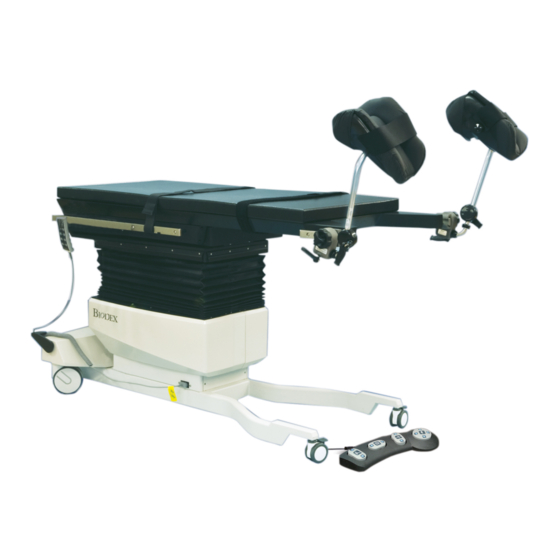
1. Introduction Intended Use The 3D Imaging C-Arm Table 820 is designed for image-guided procedures where stability, access, and precise, quiet, vibration-free positioning are essential. It features motorized actuation of height, X-Y tabletop, lateral roll and Trendelenburg motions. Functional design provides complete access with reduced radiation exposure to clinicians. - Page 9 Figure 1.1. Parts and Adjustment Mechanisms Standard Parts and Adjustments: Hand-Held Controller Foot Controller Body Restraining Straps Accessory Rail Low Profile Base Open Leg Design Accessory Rail Head End Locking Brakes and Swivel Casters Left and Right Knee Crutches (Optional Component) 10.
-
Page 10: Operating Instructions
2. Operating Instructions CAUTION: Refer to instruction manual before operating or servicing system. This table can be operated with the power cord connected to an outlet or by using the battery. The battery recharges automatically while the table is plugged into an outlet even if the table is being used. CAUTION: Hospital grade plug to be plugged into a hospital grade receptacle only to achieve grounding reliability. - Page 11 Figure 2.1. Locking Brakes and Swivel Casters. Figure 2.2. Ergonomically designed leg supports to allow easy access and comfort.
-
Page 12: Using The Hand-Held Controller
Using the Hand-Held Controller CAUTION: Before adjusting the tabletop position, ensure the patient is secure to the tabletop with patient safety restraint straps. The hand-held controller may be used to adjust table height, Trendelenburg/Reverse Trendelenburg, lateral roll and X-Y positioning. To adjust table position, press and hold the appropriate button and release to stop movement. -
Page 13: Tabletop Extensions
Figure 2.4. Foot Controller Tabletop Extensions The Radiolucent Extension is used to extend the table when transferring a patient and can be used during imaging as it contains no metal cross members. The Head-End Extension is also used to extend the length of the table but is non-viewable and cannot be used for imaging. The radiolucent leg extension inserts into access doors below the abdominal seat section. -
Page 14: Disposable Skirt (Optional Component)
Disposable Skirt (Optional Component) The Biodex 3D Imaging C-Arm Table can be ordered with the optional Plastic Sanitary Skirts to protect the table bellows from patient blood and other liquids. The table has magnetic clips located immediately above the bellows. Secure the skirt to the clips as described below: 1. -
Page 15: Pole (Optional Component)
I.V. Pole (Optional Component) The adjustable height I.V. pole should be installed onto the O.R. accessory rail. Loosen the I.V. pole locking knob at the base of the slide block and slide the block and pole onto the accessory rail until it is in the desired position. Tighten the locking knob to secure the pole. To adjust the height of the I.V. -
Page 16: Maintenance And Cleaning
3. Maintenance and Cleaning Follow the below instructions for the care and cleaning of your table and patient pads: 1. Clean the pad and exterior surfaces with a mild detergent solution, such as “Parker Laboratories Protex Disinfectant” or any disinfectant that does not contain bleach. 2. -
Page 17: Specifications
4. Specifications Dimensions: 103.75" l x 26" w (246 x 66 cm) with OR accessory rails Tabletop: 103.75" l x 24" w (246 x 61 cm) Radiolucent Area: 3D Imaging Area: 22.5" l x 24" w (57.1 x 61 cm) Other Tabletop Area: Radiolucent Extension: 29"... - Page 18 Optional Components 056-862 Battery and Charging Unit, 115 VAC 056-863 Battery and Charging Unit, 230 VAC 056-851 Drain Bag Frame 056-850 IV Pole, Rail Mounted 056-853 Crutch, Knee, Simplicity (pair) 058-862 Stirrups, PAL with boot pad (pair) 058-863 Arm Board, Dura Board with pad (pair) 058-865 Arm Board, Standard (pair) 058-866...
- Page 19 No material in this document may be copied by any third party, or used for any commercial purpose or for any use other than that granted to the purchaser without the written permission of Mirion Technologies, Inc. Biodex Medical Systems, Inc., 20 Ramsey Road, Shirley, New York 11967-4704 Tel: 800-224-6339 (Int’l 631-924-9000) Fax: 631-924-9241 www.biodex.com.
Need help?
Do you have a question about the 058-820 and is the answer not in the manual?
Questions and answers