
Subscribe to Our Youtube Channel
Related Manuals for biodex 950-430


Summary of Contents for biodex 950-430
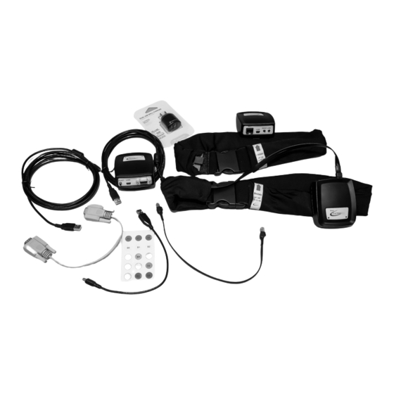
- Page 1 BIODEX VIBROTACTILE SYSTEM For use with the Balance System SD and BioSway (Win CE versions) INSTALLATION AND OPERATING MANUAL 950-430 FN: 15-462 Rev A 5/16...
- Page 2 This manual contains operating procedures for the following Biodex products: 950-430 VibroTactile System, 115 VAC 940-440 Balance System SD, 12.1” Display, 115 VAC 950-460 BioSway 12.1” LCD with Tabletop Stand and Case, 115V/230V 50/60V 950-461 BioSway 12.1” LCD with Tabletop Stand, 115V/230V 50/60V Contact Information Biodex Medical Systems, Inc.
-
Page 3: Table Of Contents
Table of Contents 1 OVERVIEW ..........................4 2 INSTALLATION ........................5 3 BATTERY AND WIRELESS CONNECTION STATUS ..............8 4 COORDINATING LINKBOXES AND TACTILEBELT BOXES ............10 5 CLINICAL APPLICATIONS ...................... 15 6 SUPPORTING RESEARCH AND SUGGESTED READING ............. 19 APPENDIX A - SPECIFICATIONS ..................... -
Page 4: Overview
In balance training, to really focus on the vestibular system, one’s visual system input needs to be temporarily eliminated. When patients close their eyes during a balance training session, the Biodex VibroTactile System provides biofeedback in the form of a “buzz” or vibration-cued signal. -
Page 5: Installation
2. Installation Software Download and Installation If you purchased your Biodex balance device in late 2015, the VibroTactile System functionality will be part of the device’s software—you just have to activate it (see below). If you have an earlier model, you can download the updated software with the VibroTactile System functionality from the Biodex website. - Page 6 Figure 2.3. There are two cables: a serial communication cable and a short USB cable (for power). Once connected, a blue light will come on indicating the LinkBox is powered. Figure 2.3 Installing the LinkBox to the back of the display. Biodex Medical Systems, Inc. © 2015...
- Page 7 Connecting and Applying the TactileBelt Two belts are provided, sized 28”-36” (71-91 cm) and 36”-48” (91-122 cm). Select for best fit. The TactileBelt Receiver boxes are the same for both and can be interchanged if needed. Use the short cable to connect the TactileBelt Receiver box to the connector on the TactileBelt. NOTE: Be sure to charge the batteries in the TactileBelt Receiver boxes for a minimum of 8 hours before use.
-
Page 8: Battery And Wireless Connection Status
“sleeping” and will not immediately connect. By clicking the RESET button the belt receiver “wakes up” and should connect correctly. Figure 3.1 TactileBelt Receiver box LED indicators. Biodex Medical Systems, Inc. © 2015... - Page 9 Charging / Power Options for TactileBelt Receiver Boxes There are two ways to charge the TactileBelt Receiver boxes: 1.) Wall outlet charger (for quickest charge) 2.) USB connection to display Figure 3.2 TactileBelt Receiver boxes can be charged with a connection to a wall outlet or to the display on the device. On-Screen Indicators The wireless reception and battery symbols on the upper left corner of the display indicate TactileBelt/LinkBox communication and TactileBelt battery status.
-
Page 10: Coordinating Linkboxes And Tactilebelt Boxes
4. Coordinating LinkBoxes and TactileBelt Boxes Configuring Equipment in Facilities with One VibroTactile System Your Biodex VibroTactile System comes with one LinkBox and two TactileBelt belts and Receiver boxes. The LinkBox will be labeled with a sticker denoting “A0”, and the two TactileBelt Receiver boxes will be labeled “A1”... - Page 11 Select TactileBelt Receiver (Box) A1. Figure 4.3 Use the dropdown menu to select a TactileBelt Receiver box. Check the label to ensure that you are holding TactileBelt Receiver box A1, and then press the LINK button on that box. The A0 LinkBox should detect and connect with the A1 TactileBelt Receiver box.
- Page 12 TactileBelt box that the LinkBox is communicating with. (In this case, TactileBelt Receiver box A1.) Figure 4.6 A Postural Stability Training screen, showing wireless connectivity and battery life of TactileBelt A1. Biodex Medical Systems, Inc. © 2015...
- Page 13 TactileBelt boxes), and then, 2) Configuring those boxes on the balance device itself. Step 1: Configuring VibroTactile System Components on Your Windows 7 or 8 Computer Begin by downloading the Vibrotactile Configuration Utility from the Biodex Software update web page: http://www.biodex.com/physical-medicine/products/software-updates Follow the prompts to install the software on your Windows 7 or 8 computer.
- Page 14 Channel B—follow the steps outlined in the previous section (“Configuring Equipment in Facilities with One VibroTactile System”) for coordinating the boxes. Figure 4.9 Coordinating the reconfigured LinkBox and TactileBelt boxes. Biodex Medical Systems, Inc. © 2015...
-
Page 15: Clinical Applications
5. Clinical Applications The Biodex VibroTactile System provides augmented feedback and cueing during balance training when the patient is performing either eyes-open or eyes-closed exercises. Vibrotactile feedback can be used as an indicator of positive reinforcement to affirm positional control. It can also indicate negative outcomes in instances where positional control is not achieved. - Page 16 Figure 5.2 Weight Shift Training mode. Limits of Stability Training In Limits of Stability training, the tactors corresponding with the on-screen targets will vibrate when the patient moves the cursor accordingly. Figure 5.3 Limits of Stability Training mode. Biodex Medical Systems, Inc. © 2015...
- Page 17 Percent Weight Bearing Training In Percent Weight Bearing training, tactors corresponding with patient movement on direction planes will vibrate when the boundary is exceeded (on-screen graphic will display a blue color) and turn off when the patient stays within the boundary (graphic will be green.) Figure 5.4 Percent Weight Bearing Training mode.
- Page 18 When vibrotactile feedback is being employed during a training session, this will be denoted at the top of the training report page (“VT Belt”). Figure 5.7 Sample of a Postural Stability Training mode report, with denotation that the VibroTactile System was activated during the training. Biodex Medical Systems, Inc. © 2015...
-
Page 19: Supporting Research And Suggested Reading
6. Supporting Research and Suggested Reading Elliott, Linda R., Michael D. Coovert, Matthew Prewett, Ashley G. Walvord, Kristin Saboe, and Ryan Johnson. 2009. A review and meta analysis of vibrotactile and visual information displays. Aberdeen Proving Ground, MD: U.S. Army Research Laboratory. Wall C 3rd. -
Page 20: Appendix A - Specifications
Current: 260 mA (when charging) Auxiliary Ports: USB (wired); LR-WPAN (wireless) Total Shipping Weight: 5 lb (2.3 kg) Warranty: One year - parts and labor For devices running on Windows CE operating systems only. Field upgrades available. Biodex Medical Systems, Inc. © 2015... -
Page 21: Appendix B - Conformance To Standards
APPENDIX B – CONFORMANCE TO STANDARDS "Mi-Wi” communication software - Copyright JD Birck, LLC United States: Contains FCC ID: OA3MRF24J40MA Canada: Contains IC: 7693A-24J40MA This equipment has been tested and found to comply with the limits for a Class B digital device, pursuant to part 15 of the FCC Rules. - Page 22 Biodex Medical Systems, Inc. © 2015...
Need help?
Do you have a question about the 950-430 and is the answer not in the manual?
Questions and answers