Advertisement
Quick Links
ULTRA PRO ULTRASOUND TABLE
INSTALLATION/ OPERATION MANUAL
058-720
058-725
B
IODEX
Biodex Medical Systems, Inc.
20 Ramsay Road, Shirley, New Y ork, 11967-4704, Tel: 800-224-6339 (In NY and Int'l, call 631-924-9000), Fax: 631-924-9241, Email: sales@biodex.com, www.biodex.com
FN: 05-277 8/05
Advertisement

Related Manuals for biodex 058-720


Summary of Contents for biodex 058-720
- Page 1 ULTRA PRO ULTRASOUND TABLE INSTALLATION/ OPERATION MANUAL 058-720 058-725 IODEX Biodex Medical Systems, Inc. 20 Ramsay Road, Shirley, New Y ork, 11967-4704, Tel: 800-224-6339 (In NY and Int’l, call 631-924-9000), Fax: 631-924-9241, Email: sales@biodex.com, www.biodex.com FN: 05-277 8/05...
- Page 2 ULTRA PRO ULTRASOUND TABLE This manual covers installation and operation procedures for the following products: #058-720 Ultra Pro Ultrasound Table, 115 VAC #058-725 Ultra Pro Ultrasound Table, 230 VAC Symbol Meaning CAUTION: Refer to instruction manual before operating or servicing system.
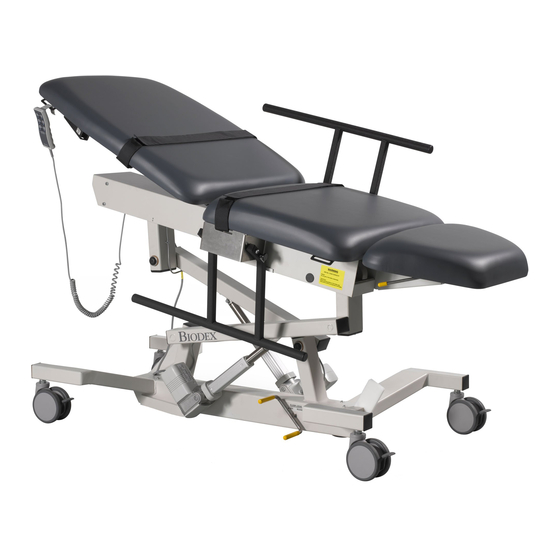
- Page 3 Naugahyde ® , two patient restraining straps with Velcro ® Figure 1. The Biodex Ultra Pro Ultrasound Table parts and hook and loop fasteners, five-inch swivel casters and a adjustment include: central locking system, accessible from either side of the table, to secure table position.
- Page 4 GENERAL SAFETY CONSIDERATIONS MOVING THE TABLE 1. Ensure table is locked and the Fowler back is securely in position before patient transfer to and from CAUTION: Remove patient before moving table. the table or wheelchair. ATTENTION: Retirer le patient avant de deplacer S’assurer que les roues sont verrouillées et que le la table.
- Page 5 CHAIR POSITIONING INSTALLING AND USING OPTIONAL ACCESSORIES The foot cushion can be lowered and the Fowler back raised to provide chair positioning. NOTE: The tools needed to install all table accessories are provided with the table. These include a 7/16" wrench, To lower the foot cushion, grasp the cushion at the end to 9/16"...
- Page 6 Vascular Scanning Arm Board (058-735) The Vascular Scanning Arm Board can be used to provide support to the patient’s arm on either side of the table. NOTE: An arm board receiving tube must be installed on both the left and right side of the table. One arm board and two receiving tubes are supplied.
- Page 7 Retractable Stirrups (#058-651) To access the stirrups: A set of sturdy Retractable Stirrups can be neatly con- 1. Lower the foot end cushion. cealed in the table frame beneath the abdominal (seat) 2. Lift up slightly on the stirrups and then slide them fully cushion.
- Page 8 Side Rails (#058-631) The side rails can be installed on both sides of the table. Each rail pivots individually to assume either the raised or lowered position. Both a left side rail and a right side rail are supplied. They must be installed on the correct side of the table.
- Page 9 Paper Dispenser (#058-610) The paper dispenser can be mounted on the head end of the table. Installing the Paper Dispenser: 1. Raise completely the Fowler back section of the table. 2. Using a 7/16" wrench, remove the two 1/4-20" hex head screws from under one side of the head end of the Fowler back cushion.
- Page 10 I.V. Pole (058-656) 4. Insert the I.V. Pole into the I.V. Pole Mounting bracket. The I. V. Pole must be installed on the patient left side of Ensure that the I.V. Pole passes through both the top the table. and bottom holes in the mounting bracket to ensure I.V. Pole stability.
-
Page 11: Maintenance
MAINTENANCE SPECIFICATIONS Dimensions: 71" l x 30" w (180.3 x 76.2 cm); 1. As required, cleanse all exterior surfaces and tabletop 35.50" w (90.2 cm) with side rails pads with a mild detergent solution. Drop-Down Leg Section: 12.6” l (32 cm) 2. - Page 12 ELECTROMAGNETIC COMPATABILITY CHART Legend – Pass x Fail q Not applicable - No requirement Test Type Result Emission EN 61000-6-3 EN 61000-6-4 EN 60601-1-2 + EN 1970 Mains terminal interference voltage – – – Interference Current – Radiated Electromagnetic field –...
- Page 13 - 13 -...
- Page 14 - 14 -...
- Page 15 - 15 -...
- Page 16 - 16 -...
- Page 17 - 17 -...
- Page 18 - 18 -...
- Page 19 - 19 -...
- Page 20 - 20 -...
- Page 21 - 21 -...
- Page 22 - 22 -...
- Page 23 IODEX Biodex Medical Systems, Inc. 20 Ramsay Road, Shirley, New Y ork, 11967-4704, Tel: 800-224-6339 (In NY and Int’l, call 631-924-9000), Fax: 631-924-9241, Email: sales@biodex.com, www.biodex.com...
Need help?
Do you have a question about the 058-720 and is the answer not in the manual?
Questions and answers