Table of Contents

Related Manuals for Daikin WCT Series


Summary of Contents for Daikin WCT Series
- Page 1 Operating & Maintenance Manual D-EOMWC01302-16EN Counter-Flow Centrifugal Chillers with Two-Stage Compressors 2200 to 3250 TONS (7750 to 11400 kW) Series Counter-Flow with Two-Stage Compressors 4500 to 6400 TONS (15830 to 22500 kW)
-
Page 2: Table Of Contents
Warranty Statement ..................82 Manufactured in an ISO Certified Facility ©2013 Daikin International. Illustrations and data cover the Daikin International product at the time of publication and we reserve the right to make changes in design and construction at anytime without notice. -
Page 3: Safety Instructions
This manual is intended for use by owner or Daikin authorized service personnel. Cautions and Warnings At several points in the manual, items of special interest or significant impact are highlighted by one of the following notices in the appropriate section of the manual. -
Page 4: Introduction
NOTE During the initial startup of the chiller the Daikin technician will be available to answer any questions and instruct in the proper operating procedures. This Daikin centrifugal chiller represents a substantial investment and deserves the attention and care normally given to keep this equipment in good working order. - Page 5 Nomenclature WCTKDCCCP2Z / KDCCCP2Z / E5426-BG-1LL / C5426-BR-1LL /134 Compressor Compressor Evaporator Condenser Refrigerant (No.1) (No.2) WCT : Water Cooled Two-Stage Centrifugal COMPRESSOR K : Frame Type of Compressor D : Shroud Pattern of 1st Stage Impeller C : Impeller Head of 1st Stage Impeller C : Shroud Pattern of 2nd Stage Impeller C : Impeller Head of 2nd Stage Impeller P2 : Motor Rating ( kW )
-
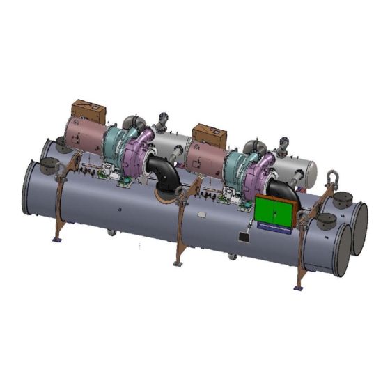
Page 6: Components And Operation
Components and Operation Figure 1, WCT Major Component Locations ECONOMIZER Circuit 1 COMPRESSOR Circuit 2 CONDENSER ECONOMIZER Circuit 1 Circuit 2 COMPRESSOR Circuit 1 EVAPORATOR Circuit 1 CONDENSER EVAPORATOR UNIT MONITOR CONTROL BOX Circuit 2 Circuit 2 Note: Evaporator nozzles may be side-by-side or over-and-under depending on model. Dual Circuit, Series Counter-flow Chillers Overview The WCT chiller has a single evaporator and a condenser. - Page 7 Figure 3, Two-Stage Vapor Compression Refrigerant Cycle (valid for each circuit) Economizer Stage Stage Evaporator Expansion Valve Condenser Subcooler Capacity Control System The motor-driven inlet guide vanes (IGV) located at the entrance to the compressor first stage impeller control the quantity of refrigerant entering the impeller thereby controlling the compressor capacity in the first-stage.
- Page 8 vapor to enter the subcooler may allow vapor to leave the condenser, thereby decreasing the efficiency of the system. Therefore, the liquid level must extend far enough above the subcooler entrance to prevent vapor within vortex, which is typically formed at high flow rates, from entering the subcooler. When the chiller is operating at load, the most reliable source of liquid refrigerant is the condenser.
-
Page 9: Lubrication System
The terms “intercooler” and “economizer” are interchangeably used in the industry for the liquid/vapor separator tank. Evaporator The evaporator is a flooded shell-and-water tube heat exchanger with refrigerant on the shell side, where chilled water getting cooler, eventually to desired target temp level at water outlet of the evaporator. When the compressor starts, it creates suction and draws some of the refrigerant gas from the evaporator, thus decreasing the pressure of the evaporator. -
Page 10: Motor Cooling
run (prelube) to provide oil to the bearings. It also runs after compressor shutdown to lubricate the bearings during coast down (postlube). During idle periods, the oil in the sump tends to absorb as much refrigerant as it can hold, depending upon the oil temperature and sump pressure. - Page 11 Figure 4, Oil & Motor Cooling and Drain Lines Oil Lubrication Line Vent Line Stage Discharge Stage Impeller Stage Impeller Compressor Stage Suction Oil Temp Control Ref from Cond Filter Oil Pressure Cooler Ref to Regulator Evap Oil Return Control Two eductor circuits are provided to properly return oil and refrigerant mixture from the refrigeration circuits to the oil sump for separation.
- Page 12 In Eductor Circuit 2, high pressure condenser gas flows continuously through the eductor inducing low pressure oil-contaminated refrigerant liquid from the evaporator through the filter to the oil sump. There are no moving parts in the eductors. They create a reduced pressure area inside which draws lubricant into the compressor.
-
Page 13: Features Of The Control Panel
Features of the Control Panel Control of leaving chilled water within a 0.5°F (0.3°C) tolerance. Systems with a large water volume and relatively slow load changes can do better. Readout of the following temperature and pressure readings: Entering and leaving chilled water temperature ... - Page 14 General Description The control panel is located on the front of the unit. There are two doors. The control panel is behind to right door. The centrifugal MicroTech control system consists of microprocessor-based controllers and a number of extension modules, which vary depending on the unit size and conformation. The control system provides all monitoring and control functions required for the controlled, efficient operation of the chiller.
-
Page 15: Controller Description
Controller Description Hardware Structure The MicroTech III control system for WCT chillers consists of a main unit controller with a number of extension input/output I/O modules, Operator touch screen, lubrication control, miscellaneous switches and field connections terminals. One of the optional BAS communication modules may be included. The MicroTech III controllers used on WCT chillers are not interchangeable with previous MicroTech II controllers. -
Page 16: System Architecture
System Architecture The overall controls architecture uses the following: One MicroTech III main controller I/O extension modules (sometimes referred to as “controllers”) as needed depending on the configuration of the unit Optional BAS interface as selected In series counter-flow system, both lead WCT chiller controller and lag WCT chiller controller are available to communicate and have optimized series counter-flow system capacity control by looking at common ELWT at lag chiller, when providing “Konex”... -
Page 17: Field Wiring Diagram
Field Wiring Diagram Figure 9, Field Wiring Diagram OMM WCT Centrifugal Chillers D-EOMWC01302-16EN - 17/84... - Page 18 Minimum wire size for 115 VAC to 220 VAC is 12 GA. for a maximum length of 50 feet. If greater than 50 feet refer to Daikin for recommended wire size minimum. Wire size for 24 VAC is 18 GA. All wiring to be installed as NEC class 1 wiring system.
-
Page 19: Operator Interface Touch Screen (Oits)
Operator Interface Touch Screen (OITS) The operator interface touch screen (OITS) is the primary device by which commands and entries into the control system are made. It also displays all controller data and information on a series of graphic screens. The control panel contains a USB port that can be used for loading information to and from the control system. -
Page 20: Navigation
Unit Controller Unit and compressor on/off switches are mounted in the control panel located adjacent to the OITS panel. The compressor on/off switch should only be used when an immediate stop is required since the normal shut down sequence is bypassed. The switch panel also has a circuit breaker that interrupts power to the cooling tower fans, valves and evaporator and condenser pumps’... - Page 21 Table 2, Unit Controller, Digital Inputs Description Signal Signal Mode Switch 0 VAC (Cool) 24 VAC (Ice or Heat) Unit OFF Switch 0 VAC (Stop) 24 VAC (Auto) Evap Flow 0 VAC (No Flow) 24 VAC (Flow) Cond Flow 0 VAC (No Flow) 24 VAC (Flow) Remote Start/Stop 0 VAC (Stop)
- Page 22 Table 6, Circuit I/O, Digital Inputs Description Signal Signal CC-DI1 Manual Off 0 VAC (Off) 24 VAC (Auto) CC-DI2 Starter Fault 0 VAC (Fault) 24 VAC (No Fault) CC-DI3 Starter Transition 0 VAC (No Transition) 24 VAC (Transition) CC-DI4 Mech High Pressure 0 VAC (High Pressure ) 220 VAC (OK) CC-DI5...
- Page 23 Figure 11, OITS Screen Layout EVAPORATOR MAIN COMPRESSOR Screen Screen Screen Press Evaporator Press Main Press Compressor Evaporator Main Compressor Detail Summary Motor CONDENSER Lubrication IGV/DDC Screen Hot Gas Press Condenser In some screen pressing the Displaying Circuit x button will switch the value to the Condenser other circuit.
-
Page 24: Screen Descriptions
Screen Descriptions Main Screens Main screens are used for viewing unit status and conditions. Figure 12, Home View Screen Main Screen The Main Screen shows the basic condition of the chiller and is the screen that is normally left on. Superimposed on a chiller schematic is: Information ... - Page 25 Table 9, UNIT STATUS Possibilities Status Text Auto Off – Ice Mode Timer Off – All Cir Disable Off – Unit Alarm Off – Keypad Disable Off – Remote Switch Off – BAS Disable Off – Unit Switch Off – Test Mode Off –...
- Page 26 Action Buttons for: Figure AUTO and STOP buttons, normal start (AUTO) and STOP button activates the normal start and shutdown sequence. These buttons are only active when the control is in the "Local Control" mode. This eliminates the possibility of inadvertently shutting off the unit locally when it is under control of a remote signal such as a BAS.
- Page 27 Table 14, Compressor Screen Pressing the Compressor button will give detailed information on the compressor (State, Inputs and Outputs). OMM WCT Centrifugal Chillers D-EOMWC01302-16EN - 27/84...
- Page 28 Figure 15, Evaporator Screen Pressing the Evaporator or Condenser button will give detailed information on the evaporator or condenser. Figure 16, Economizer Screen Pressing the Economizer button will give detailed information on the Economizer. OMM WCT Centrifugal Chillers D-EOMWC01302-16EN - 28/84...
-
Page 29: Set Screens
Figure 17, Expansion Screen Pressing the Expansion button will give detailed information on the Expansion. SET Screens The set screens on the Interface Panel are used to input the many setpoints associated with equipment of this type. MicroTech III provides an extremely simple method for accomplishing this. (NOTE: If the Interface Panel is unavailable, the unit controller can be used to change setpoints.) Appropriate setpoints are factory set and checked by DaikinService or Factory Authorized Service Company during commissioning. - Page 30 O = Operator level password is 5321 M = Manager level (password is reserved for Daikin service personnel) T = Technician level (password is reserved for authorized technicians) 4. Press the appropriate numbers in the numeric keyboard to enter the password. There is a small delay between pressing the keypad and recording the entry.
- Page 31 7. Additional setpoints can be changed by selecting another setpoint on the screen or by selecting an entirely new group of setpoints. Explanation of Setpoint Groups Each of the seven setpoint group of screens are detailed in the following section. In many cases the setpoint content is obvious and no explanation is included.
- Page 32 Table 11, WATER Setpoint Settings Pass- Description Default Range Comments word 35.0 to 80.0 F Cool LWT Evaporator LWT setpoint in COOL mode 44. 0F 15.0 to 35.0 F Ice LWT 25. 0F Evaporator LWT setpoint in the ICE mode 100.0 to 150.0 F Heat LWT Condenser LWT setpoint in HEAT (Templifier) mode...
- Page 33 Table 12, MODE Setpoint Settings Pass- Description Default Range Comments word OFF, everything is off. ON, Evap pump on, comp, Unit Enable OFF, ON cond pump and tower on as required to meet LWT Unit Mode COOL COOL, ICE, HEAT, TEST Selects from MODES in SP4 Control Source LOCAL...
- Page 34 MOTOR Setpoint Screen Figure 21, MOTOR Setpoint Screen Table 13, MOTOR Setpoint Settings Pass- Description Default Range Comments word ON sets %RLA at 0% for 4 mA external signal and at Demand Limit Enable OFF, ON 100% RLA for 20 mA signal Minimum Amps 20 to 80% % RLA below which unloading is inhibited...
- Page 35 Cooling TOWER Fan Settings Figure 22, TOWER Fan Setpoint Screen (See page 3635 for complete explanation.) Table 14, Tower Fan Settings Pass- Description Default Range Comments word None: No tower fan control None, Tower Control None Temperature: Fan and valve controlled by EWT Temperature, Lift Lift: Fan and valve controlled by lift pressure Time delay between stage up/down event and next...
- Page 36 Explanation of Tower Control Settings MicroTech III control can control cooling tower fan stages, a tower bypass valve, and/or a tower fan VFD if the chiller has a dedicated cooling tower. The Tower Bypass Valve position will always control the Tower Fan Staging if Valve Setpoint, Stage Setpoint is selected.
- Page 37 Tower Fan Staging With Bypass Valve Controlling Minimum EWT (VALVE SP) 1) TOWER SETPOINT Screen a) Tower Control. Select TEMP if control is based on condenser EWT or LIFT if based on compressor lift expressed in psi. b) Valve/VFD Control. Select Valve SP for control of bypass valve based on temperature or lift. c) Tower Stages.
- Page 38 x) Error Gain, Set the control gain for error. Default is 25. xi) Slope Gain, Set the control gain for slope. Default is 25. NOTE: Setpoints Error Gain and Slope Gain are site specific dealing with system fluid mass, component size and other factors affecting the reaction of the system to control inputs. These setpoints should be set by personnel experienced with setting up this type of control.
- Page 39 Fan VFD, No Bypass Valve (VFD STAGE) The fan VFD mode assumes the tower is driven by one large fan. Set up is as above except in SETPOINT, TOWER, Tower bypass Valve/Fan VFD, VALVE/VFD is selected. Unit Controller Supplements to Tower Control The following is intended to clarify the Tower: Error Gain and Slope Gain set points found on under the OITS VALVE group of setpoints, and on the Unit controller mask “SET TOWER Stage #1 On (Temp).
- Page 40 Figure 24, Tower Bypass VALVE Setpoint Screen Table 15, Tower Bypass VALVE Setpoints Pass- Description Default Range Comments word None: No tower valve or VFD None, Valve Valve Setpoint: Valve controls to VALVE SP3(4) & 5(6) Setpoint, Valve Valve Stage: Valve control setpoint changes to fan stage Valve/VFD Control None Stage, VFD...
- Page 41 ALARMS Setpoint Figure 25, ALARMS Setpoint Screen Table 15, ALARM Setpoints Description Default Range Pass-word Comments Min evap pressure – inhibit loading Low Evap Pressure-Inhibit 33 psi 20 to 45 psi Min evap pressure – unload compressor Low Evap Pressure-Unload 31 psi 20 to 45 psi Min evap pressure –...
- Page 42 TIMERS Setpoint Figure 26, TIMERS Setpoint Screen Table 16, TIMER Setpoints Pass- Description Default Range Comments word Evap Recirculate 0.5 min 0.2 to 5 min Time that evaporator pump must run before compressor start Start-Start 40 min 15 to 60 min Time from when compressor starts to when it can start again Stop-Start 3 min...
-
Page 43: Interface Screen
Interface Screen Figure 27, Service Screen Pressing Interface from any screen accesses the Interface screen. While containing information and activity buttons for the service technician, it also has valuable information for the operator. The touch screen software version number shown in the upper right corner. The Operating Manual button will access the operating and maintenance manual for the unit. -
Page 44: Trend Screens
Trend Screens Figure 28, History Trend Graph The Trend Overview allows the user to view the various parameters listed on the lower of the screen. The temperature, % and Pressure scale are on the left. The screen can display trend history for 8 hour, 2 hour or 20-minute periods by pressing 8 hour, 2 hour, or 20 min respectively from the default 1 hour. - Page 45 Figure 29, Alarm History The Alarm History lists the alarms with the most current on top with date stamp, action taken and the cause of the alarm. This screen is also used to download the Alarm History shown above. To download alarm history connect a USB portable storage device to the USB port located in the unit control box adjacent to the OITS, press the copy alarm data button, then select location to save the file.
-
Page 46: Clearing Alarms
ACTIVE ALARM Screen Figure 30, Active Alarms The Active Alarm screen is accessible when an active alarm exists on the unit by pressing the animated red alarm signal on any screen. Alarms are arranged in order of occurrence, with the most recent on top. Once the abnormal condition is corrected, pressing the "Clear Alarm"... - Page 47 Fault Alarms All fault alarms require a manual reset. Table 17, Fault Alarm Description Description Occurs When: Action Taken Low Evaporator Pressure Evaporator Press < Low Evap Pressure SP Rapid Stop High Condenser Pressure Cond Press > High Condenser Pressure SP Rapid Stop Compressor state = PRELUBE for 30 sec after Prelube Vanes Open No Start...
- Page 48 Table 18, Problem Alarm Description Description Occurs When: Action Taken Reset Low Evaporator Pressure Pressure < Low Evap Pressure– Evap Press rises Inhibit loading – Inhibit Loading Inhibit setpoint above (SP + 3psi) Low Evaporator Pressure Pressure < Low Evap Pressure– Evap Press rises Unload –...
-
Page 49: Using The Controller
Using the Controller Figure 31, Display and Keypad Layout Home Back Navigation wheel Display The keypad/display consists of a 5-line by 22-character display, three buttons (keys) and a “push and roll” navigation wheel. There is an Alarm Button, Menu (Home) Button, and a Back Button. -
Page 50: Navigating
displayed to the far right of the line to indicate it is a “jump” line and the entire line is highlighted when the cursor is on that line. NOTE - Only menus and items that are applicable to the specific unit configuration are displayed. - Page 51 (up) on the page. The faster the wheel is turned the faster the cursor moves. Pushing the wheel acts as an “Enter” button. Three types of lines exist: Figure Menu title, displayed in the first line as in Link (also called Jump) having an arrow ( ...
- Page 52 to jump to the next screen. With the first line highlighted, press the wheel to enter edit mode. Rotate wheel until AlmClr is set to On, then press wheel to clear the alarms. OMM WCT Centrifugal Chillers D-EOMWC01302-16EN - 52/84...
- Page 53 Screen Content Figure 35, No Password View Screens Menu Level 1 Menu Level 2 Menu Level 3 Enter Password Enter PW Unit Status Active Setpoint Evap Leaving Water Temp Unit Mode Time Until Restart Compressor 1 Cycle Time Remaining Compressor 2 Cycle Time Remaining Alarms Alarm Active Active Alarm 1...
- Page 54 Figure 36, Operator View Screen Menu Level 1 Menu Level 2 Menu Level 3 Menu Level 4 Enter Password Quick Menu View/Set Unit Status/Settings Set-Up Temperatures Date/Time/Schedules Power Conservation Alarm Limits Ctrlr IP Setup Design Conditions Menu Password View/Set Circuit Circuit #1 Circuit #2 Data...
- Page 55 Figure 37, Manager View Screen Menu Level 1 Menu Level 2 Menu Level 3 Menu Level 4 Enter Password Quick Menu View/Set Unit Status/Settings Set-Up Temperatures VFD Setup Date/Time/Schedules Power Conservation Alarm Limits Calibrate Sensors Configuration Ctrlr IP Setup Design Conditions Evap Approach @ Design Cond...
- Page 56 Alarm Log Unit Status/Settings Circuit 1 Status/Settings Circuit 2 Status/Settings Scheduled Maintenance Manual Control Unit Circuit 1 Compressor 1 Circuit 2 Compressor 1 Commission Unit About Chiller Configure Unit Set-Up Date/Time/Schedules Power Conservation Alarm Limits Calibrate Unit Sensors Calibrate Circuit Sensors Ctrlr IP Setup Alarm Active Alarm Log...
-
Page 57: Setpoints
Setpoints Table 20, Unit Setpoints Description Default Range Password Unit Unit Enable OFF, ON Number of Cir 1 to 2 Number of Comp 1 to 2 Pbus Address Unit Mode COOL COOL, ICE, HEAT, TEST Cool, Cool w/Glycol, Cool/Ice, Available Modes COOL Ice, Cool/Heat, Heat Control Source... - Page 58 Description Default Range Password Global Circuit Electronic Expansion Valve Exv Control Cond Delta T Cond Delta T, Evap Delta T 55.5 ∆°C 0 to 55.5 ∆°C SH Drop out WCC Cap Ratio 0.45 to 0.70 Timers Start-Start 40 min 15 to 60 min Stop-Start 3 min 3 to 20 min...
- Page 59 Description Default Range Password High Discharge Temperature Alarm 194 °F 120 to 240 °F High Discharge Temperature Load 170 °F 120 to 240 °F High Pressure Alarm 140 psi 120 to 240 psi Minimum RLA 5 to 80 % Oil No Start Delta Temperature 22.2 °C 16.6 to 33.4°C Maximum Oil Feed Temperature...
- Page 60 Description Default Range Password IGV Manual Position DDC Manual Position IGV Maximum Position Stop 110% 100 to 130 IGV Start Position 0 to 40% DDC Minimum Position 0 to 40% IGV Minimum Position 0 to 40% IGV Load Gain 0.01 to 100 IGV Unload Gain 0.01 to 100 Save Curve...
- Page 61 Description Default Range Password Suction Temp Offset -5.0 to 5.0 Discharge Temp Offset -5.0 to 5.0 Oil Feed Temp Offset -5.0 to 5.0 Oil Sump Temp Offset -5.0 to 5.0 Econ Press Offset -100.0 to 100 Oil Feed Press Offset -100.0 to 100 Oil Sump Press Offset -100.0 to 100...
-
Page 62: Condenser Water
Condenser Water Cooling towers used with Daikin centrifugal chillers are normally selected for maximum condenser inlet water temperatures between 75°F and 90°F (24°C and 32°C). Lower entering water temperatures are desirable from the standpoint of energy reduction, but a minimum does exist. - Page 63 For example; at 44F LCHWT, 10-degree F chilled water Delta-T, and 50% full load operation, the entering condenser water temperature could be as low as 56 F. The operating strategy for cooling tower fans requires some analysis. Regardless of power consumption considerations, the minimum allowable entering condenser water temperature must be maintained.
-
Page 64: Maintenance
For qualified assistance, contact your local Daikin service location. Failure to do so can cause severe compressor damage. After the system is once placed into operation, no additional oil is required except in the event that repair work becomes necessary to the oil pump or unless a large amount of oil is lost from the system due to a leak. - Page 65 Daikin has done extensive testing in conjunction with refrigerant and oil manufacturers and has established guidelines to determine action levels and the type of action required. Table 22 on page 66 gives the upper limits for metals and moisture in the polyolester lubricants required by Daikin chillers. OMM WCT...
- Page 66 For TAN above 0.19, change lubricant, lubricant filter, and filter-drier and resample at normal interval In general Daikin International does not recommend changing oil and filters on a periodic basis. The need should be based on a careful consideration of oil analysis, vibration analysis and knowledge of the operating history of the equipment.
- Page 67 In conclusion, a single element of an oil analysis should not be used as the basis to estimate the overall internal condition of a Daikin chiller. The characteristics of the oil and refrigerant, and knowledge of the interaction of wear materials in the chiller must be considered when interpreting a wear metal analysis.
- Page 68 Refrigerant Cycle Maintenance of the refrigerant cycle includes maintaining a log of the operating conditions, and checking that the unit has the proper lubricant and refrigerant charge. At every inspection, all system pressures and temperatures should be recorded on a copy of the Log Sheet on page 92.
-
Page 69: Equipment Cleaning And Preserving
It is recommended that the service of a reliable water treatment company be used. Daikin assumes no responsibility for the results of untreated or improperly treated water. 6. Drain water from the chiller and remove water heads at least once a year to inspect the condenser and evaporator tubes and clean if required. - Page 70 CAUTION Acid cleaning of tubes must only be performed by authorized and trained service personnel. For qualified assistance, contact your local Daikin Factory Service office. Types of In-Tube Fouling : 1) Biological : The attachment of macro- and/or micro-organisms to the heat transfer surfaces.
-
Page 71: Annual Startup
Examples of harmful deposits (tubercles) are: High amount of iron or metallic deposits due to corrosion occurring inside the iron/carbon steel piping in the water circuit can be carried by the water to the tubes. These metallic deposits often adhere or fuse themselves to the tube. -
Page 72: Repair Of System
Repair of System NOTE It is at utmost importance that all local, national, and international regulations concerning the handling and emission of refrigerants are observed. Pumping Down If a major repair is necessary on the chiller other than condenser, refrigerant charge can be isolated and stored in the condenser of the related circuit by pumping down. - Page 73 Leak Testing After a service repair, the unit must be checked for leaks prior to recharging the complete system. This can be done by charging enough refrigerant R-134a into the system to build the pressure up to approximately 10 psig (69 kPa) and adding sufficient dry nitrogen to bring the pressure up to a maximum of 125 psig (860 kPa).
-
Page 74: Charging The System
12) If the vacuum hold test fails use Table 32 to determine if the failure is due to a leak or water/moisture in the unit. If the vacuum level rises above water saturation point then do another leak test. If it stops at water saturation temperature, continue evacuation until dry or source determined. - Page 75 Stand the refrigerant cylinder with the connection up. In order to avoid possibility of freezing the liquid within the evaporator tubes when charging an evacuated system, only refrigerant vapor from the top of the refrigerant cylinder must be admitted first. Just before connecting the charging line to the service valve on top of the evaporator, open the valve on the cylinder and purge any air in the charging line.
- Page 76 condenser sight glass should be about an inch above the subcooler trough cover plate without any condenser tubes at the bottom immersed in the liquid, and about an inch above the evaporator tubes all wetted but not totally immersed. Capacity of the chiller and discharge superheat should also be monitored through the main control console in order to manage the process.
-
Page 77: Maintenance Schedule
Maintenance Schedule Maintenance Check List Item I. Unit · Operational Log · Analyze Operational Log · Refrigerant Leak Test Chiller · Test Relief Valves or Replace II. Compressor · Vibration Test Compressor A. Motor · Meg. Windings (Note 2) · Ampere Balance (within 10% at RLA) ·... - Page 78 Daikin's high efficiency heat exchangers have very low design approach temperatures, in the order of one to one and one half degrees F.
- Page 79 EVAPORATOR : SYMPTOM RESULTS Possible Cause Remedy High Evaporator Approach Temperature with Low Charge Check for leaks and add charge High Discharge Temperature EXV problem Remove obstruction High Evaporator Approach Temperature with Dirty or restricted Clean Evaporator Tubes and/or Normal Discharge Temp evaporator tubes Check water conditioning Low Evaporator water leaving...
- Page 80 SYMPTOM RESULTS Possible Cause Remedy Small Evaporator Capacity Loss and high Evaporator pass baffle Stop unit operation, drain water, remove gasket damage water pressure Evaporator approach water box and replace gasket difference between temperature water entering and leaving Fluctuating unsteady Pass baffle gasket damage Air in water boxes Vent any air from the chiller water boxes...
-
Page 81: Perating Log Sheet
PERATING LOG SHEET WCT CENTRIFUGAL CHILLER WCT Model No.__________ Chiller ID No. __________ Date __________ Operator ________________ DATA POINT VALUE SOURCE EVAPORATOR WATER PRESSURE DROP ACROSS CHILLER Gauges ENTERING CHILLED WATER TEMPERATURE VIEW #2 LEAVING CHILLED WATER TEMPERATURE VIEW #2 DELTA TEMPERATURE (LINE 2 –... -
Page 82: Service Programs
3 to 4 weeks of normal operation on a new installation, and on a regular basis thereafter. Daikin offers a variety of maintenance services through the local Daikin service office, its worldwide service organization, and can tailor these services to suit the needs of the building owner. Most popular among these services is the Daikin Comprehensive Maintenance Contract. - Page 85 The present publication is drawn up by of information only and does not constitute an offer binding upon Daikin Applied Europe S.p.A.. Daikin Applied Europe S.p.A. has compiled the content of this publication to the best of its knowledge. No express or implied warranty is given for the completeness, accuracy, reliability or fitness for particular purpose of its content, and the products and services presented therein.
Need help?
Do you have a question about the WCT Series and is the answer not in the manual?
Questions and answers
software für WCT-5001 Digital Wildlife Camera (die beiliegende Mini-/CD/DVD ist hier **** lesbar)