Table of Contents
Advertisement
Quick Links
Advertisement
Table of Contents

Related Manuals for Daikin WCT


Summary of Contents for Daikin WCT
- Page 1 Installation, Operation and Maintenance Manual D-EIMWC01308-16EN Counter-Flow Centrifugal Chillers with Two-Stage Compressors 2200 to 3250 TONS (7750 to 11400 kW) Series Counter-Flow with Two-Stage Compressors 4500 to 6400 TONS (15830 to 22500 kW) HFC - 134a Original Instructions...
-
Page 2: Table Of Contents
Table of Contents Safety Instructions ................... 4 Introduction ..................... 6 Installation ....................... 8 Receiving and Handling ....................... 8 Rigging ..........................9 Location and Mounting ...................... 10 System Water Volume ......................11 Low Condenser Water Temperature Operation (Needs to be updated) ......11 Water Piping ........................ - Page 3 The entire content is protected by Daikin copyright. Manufactured in an ISO Certified Facility ©2013 Daikin. Illustrations and data cover the Daikin product at the time of publication and we reserve the right to make changes in design and construction at anytime without notice.
-
Page 4: Safety Instructions
Safety Instructions The following recommendations should be carefully observed as part of installation, operation, maintenance or service. This equipment must be installed by trained and qualified personnel experienced in the installation of similar centrifugal chillers. This manual contains important information on operation, safety, maintenance, installation, service and warranty. - Page 5 Description of the labels applied to the electrical panel Unit Control Panel 1 – Non flammable gas symbol 6 – Unit characteristics technical 2 – Electrical hazard symbol 5 – Unit nameplate data 3 – Gas type 7 – Emergency stop 4 –...
-
Page 6: Introduction
WCT chiller is suitably designed for series counter-flow, which two WCT unit is connecting in series and work as one chiller. The driveline of the WCT is made up of two two-stage compressors, each with a gear set and a 2- pole, induction semi-hermetic motor. - Page 7 1 : Number of Passes L : Water Inlet Nozzle Location (R = Right Inlet ; L= Left Inlet) L : Nozzle Configuration REFRIGERANT 134 : Refrigerant Type ( 134 = HFC-134a ); WCT is for R134a only. D-EIMWC01308-16EN - 7/40...
-
Page 8: Installation
Receiving and Handling The unit should be inspected immediately after receipt for possible damage. All Daikin centrifugal water chillers are shipped ex-factory and all claims for handling and shipping damage are the responsibility of the consignee. Insulation corners from the evaporator's rigging hole locations are shipped loose and should be glued in place after the unit is finally placed. -
Page 9: Rigging
See the certified dimension drawings included in the job submittal for the center of gravity of the unit. Consult the local Daikin sales office for assistance if the drawings are not available. The unit can be lifted by fastening the rigging shackles to the six corners of the unit where the rigging eyes are located. -
Page 10: Location And Mounting
Location and Mounting The unit must be mounted on a concrete or steel base which is level end-to-end to within ¼” (6.4 mm) and must be located to provide service clearance at one end of the unit for possible removal and replacement of evaporator and/or condenser tubes, and if necessary, to permit brush cleaning of evaporator and condenser tubes as required. -
Page 11: System Water Volume
The resultant lower condensing temperature will improve chiller performance. WCT chillers are equipped with electronic expansion valves (EEV) and will operate with entering condenser water temperatures as low as calculated by the following equation and shown in the chart following. -
Page 12: Water Piping
It is also possible to build up a frequency beat due to the slight difference in the operating rpm of the pump motor and the Daikin centrifugal motor. Daikin encourages the use of four-pole pump motors. Both the condenser and chilled water pumps’ discharge connections should be located to supply water through the chiller at positive pressure. - Page 13 eliminator sections in the condenser inlet and outlet water piping. But they can be required where noise and vibration are critical or if spring isolators are used. Vessel Drains at Start-up Unit vessels are equipped with ball-type drain valves in the bottom of each head chamber and shipped with the valves open.
-
Page 14: Thermal Insulation
Cooling Towers Check the condenser water flow rate to be sure that it conforms to the system design. Some form of temperature control is also required if an uncontrolled tower can supply water below about 65F (18C). A tower bypass valve is recommended. Unless the system and the chiller unit are specifically designed for condenser bypass or variable condenser flow, it is not recommended, since low condenser flow rates can cause unstable operation and excessive tube fouling. - Page 15 Field Insulation Guide Figure 5, Insulation Requirements (Bubble components require insulation) CONDENSER CONDENSER Circuit 2 Circuit 1 BACK VIEW EVAPORATOR Circuit 1 EVAPORATOR Circuit 2 ISOMETRIC VIEW D-EIMWC01308-16EN - 15/40...
- Page 16 Table 2, Insulated Parts Description INSULATED PARTS THICKNESS Probable Surface BUB. DESCRIPTION ( Depend on Temperature in Rating Customer) Operation USE SHEET INSULATION 0.75” 36 – 45 F ( 2 – 7 MOTOR BARREL- BACK PLATE TO GEAR HOUSING 0.75” EVAPORATOR SHELL- TUBESHEET TO TUBESHEET 36 –...
-
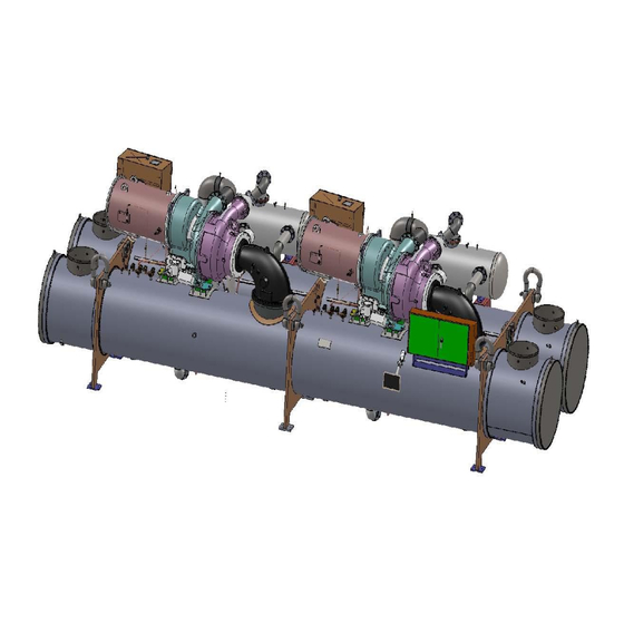
Page 17: Weights And Dimensions
Weights and Dimensions Figure 6, Unit Overall Dimensions Y(+) Y(+) X(+) Z(+) Figure 7, Unit Mounting Feet, Top Sectional View (Position of Center of Gravity relative to (0,0,0) changes depending on Unit Size) CENTER OF GRAVITY (0, 0, 0) ORIGIN OF COORDINATES (Bottom-left corner of evaporator feet opposite to compressor suction) D-EIMWC01308-16EN - 17/40... - Page 18 Table 3, Weights and Dimensions Approximated Water Volumes per Chiller Overall Dimensions Approximated Weights per Chiller Condenser Evaporator Unit COG (OPERATING) Water Water volume of volume of Total Total Shipping Operating Refrigerant water water water water Overall Overall Overall Shells Weight Weight Charge...
- Page 19 81'100 107'200 6'550 1'050 1'010 C4224-D/E4824-C (36'700) (48'500) (3'000) (1'790) (4'040) (2'220) (3'880) (9'436) (3'167) (3'148) (3'601) (1'570) (1'327) 80'800 106'600 6'850 1'050 C4224-D/E4824-D (36'600) (48'200) (3'100) (1'790) (4'040) (2'220) (3'700) (3'436) (3'167) (3'148) (3'601) (1'575) (1'331) 85'600 110'200 6'650 1'250 1'100 C4226-B/E4826-B...
- Page 20 91'400 110'000 6'500 1'490 1'060 C4824-B/E4824-B (41'300) (49'800) (3'000) (2'200) (5'730) (2'220) (4'060) (9'436) (3'167) (3'300) (3'611) (1'730) (1'321) 91'000 109'500 6'750 1'490 1'010 C4824-B/E4824-C (41'200) (49'500) (3'100) (2'200) (5'730) (2'220) (3'880) (9'436) (3'167) (3'300) (3'610) (1'726) (1'331) 90'700 109'000 7'050 1'490 C4824-B/E4824-D...
- Page 21 (42'000) (50'900) (3'400) (2'200) (6'030) (2'220) (3'820) (10'058) (3'167) (3'300) (4'018) (1'655) (1'329) 92'900 112'000 6'900 1'470 1'100 C4826-C/E4826-B (42'000) (50'700) (3'200) (2'200) (5'640) (2'220) (4'220) (10'058) (3'167) (3'300) (4'018) (1'628) (1'321) 92'500 111'500 7'200 1'470 1'050 C4826-C/E4826-C (41'800) (50'400) (3'300) (2'200) (5'640)
- Page 22 93'600 122'000 8'000 1'490 1'250 C4824-C/E5424-D (42'300) (55'200) (3'600) (2'200) (5'730) (2'780) (4'800) (9'436) (3'362) (3'300) (3'601) (1'674) (1'372) 93'900 121'900 7'200 1'310 1'380 C4824-D/E5424-B (42'500) (55'100) (3'300) (2'200) (5'020) (2'780) (5'310) (9'436) (3'362) (3'300) (3'602) (1'645) (1'368) 93'400 121'200 7'600 1'310 1'320...
- Page 23 (43'300) (56'500) (3'700) (2'200) (5'260) (2'780) (5'250) (10'058) (3'362) (3'300) (4'018) (1'566) (1'361) 95'100 124'200 8'550 1'370 1'300 C4826-D/E5426-D (43'000) (56'200) (3'900) (2'200) (5'260) (2'780) (4'970) (10'058) (3'362) (3'300) (4'018) (1'575) (1'366) 100'800 133'100 7'500 1'640 1'380 C5424-B/E5424-B (45'600) (60'200) (3'400) (2'750) (6'280)
- Page 24 (1'482) Notes: Drawings and data included in this section are for rough layout purposes only. Detailed certified drawings, as .pdf or .dwg files, are available from the local Daikin sales office. Do not use catalog drawings for final construction These data are for reference only and do not include options (like different tube type) Certified drawing will show data for the specific unit.
-
Page 25: Relief Valves
Lubrication System Emkarate RL68H Polyolester Oil must be used in the centrifugal two-stage compressor. The nominal oil charge for K compressor is 22 gallons. An internal oil sump is part of the compressor and contains a 750 W submersible fixed-speed oil pump and a 1.0 kW immersion-type oil heater that is thermostatically controlled. - Page 26 Single Vent Line per Relief Valve WCT units have relief valve settings of 200 psig and resultant valve discharge capacities of 75.5 lbm air/min. Using the formulas in ASHRAE Standard 15 defines the maximum length of discharge vent piping downstream of the pressure relief valve in Table 6.
- Page 27 Pumpdown To facilitate compressor service, all Daikin centrifugal chillers are designed to permit pumpdown and isolation of the entire refrigerant charge in the unit’s condenser. In no case would a combination of evaporator and condenser sizes require more refrigerant than the pumpdown capacity of the condenser.
-
Page 28: Electrical
Wiring, fuse and wire size (must be in accordance with the National Electric Code (NEC). Standard NEMA motor starters require modification to meet Daikin specifications. Refer to Daikin Specification R35999901. Power wiring to compressors must be in proper phase sequence. Motor rotation is set up for clockwise rotation facing the motor end with phase sequence of U-V-W or 1-2-3. -
Page 29: Control Power Wiring
It is the installing contractor's responsibility to insulate the compressor motor terminals when the unit voltage is 600 volts or greater. This is to be done after the Daikin start-up technician has checked for proper phase sequence and motor rotation. - Page 30 In the event a transformer supplies control voltage, it must be rated at 3 KVA, with an inrush rating of 12 KVA minimum at 80% power factor and 95% secondary voltage. For control wire sizing, refer to NEC Articles 215 and 310. In the absence of complete information to permit calculations, the voltage drop should be physically measured.
-
Page 31: Field Wiring Diagram
Surge Capacitors All low voltage units (except those with solid state starters or VFDs) are supplied with standard surge capacitors to protect compressor motors from electrical damage resulting from high voltage spikes. For free-standing starters, factory or customer supplied, the capacitors are mounted in the motor terminal box and must be connected to the motor terminals with leads less than 18 inches (460 mm) long when the motor is being wired. - Page 32 Minimum wire size for 115 VAC to 220 VAC is 12 GA. for a maximum length of 50 feet. If greater than 50 feet refer to Daikin for recommended wire size minimum. Wire size for 24 VAC is 18 GA. All wiring to be installed as NEC class 1 wiring system.
-
Page 33: Prestart System Checklist
Minimum system load of 80% of machine capacity available for testing and adjusting controls ....................... Note: The checklist must be completed and sent to the local Daikin service location two weeks prior to start. D-EIMWC01308-16EN - 33/40... -
Page 34: Important Information Regarding The Refrigerant Used
Important information regarding the refrigerant used This product contains fluorinated greenhouse gase. Do not vent gases into the atmosphere. Refrigerant type: R134a value: 1430 GWP = global warming potential The refrigerant quantity is indicated on the unit name plate. Periodical inspections for refrigerant leaks may be required depending on European or local legislation. Please contact your local dealer for more information. - Page 35 Factory and Field charged units instructions (Important information regarding the refrigerant used) The refrigerant system will be charged with fluorinated greenhouse gases. Do not vent gases into the atmosphere. 1 Fill in with indelible ink the refrigerant charge label supplied with the product as following instructions: the refrigerant charge for each circuit (1;...
- Page 36 Formula to calculate the greenhouse gas emission: GWP value of the refrigerant x Total refrigerant charge (in kg) / 1000 Use the GWP value mentioned on the greenhouse gases label. This GWP value isbased on the 4th IPCC Assessment Report. The GWP value mentioned in the manual might be outdated (i.e. based on the 3rd IPCC Assessment Report) Field charged units instructions (Important information regarding the refrigerant used)
- Page 37 NOTICE In Europe, the greenhouse gas emission of the total refrigerant charge in the system (expressed as tonnes CO equivalent) is used to determine the maintenance intervals. Follow the applicable legislation. Formula to calculate the greenhouse gas emission: GWP value of the refrigerant x Total refrigerant charge (in kg) / 1000 Use the GWP value mentioned on the greenhouse gases label.
- Page 38 Disposal The unit is made of metal and plastic parts. All these parts must be disposed of in accordance with the local regulations in terms of disposal. Lead batteries must be collected and taken to specific refuse collection centres. D-EIMWC01308-16EN - 38/40...
- Page 39 D-EIMWC01308-16EN - 39/40...
- Page 40 Specification are subject to change without prior notice. Refer to the data communicated at the time of the order. Daikin Applied Europe S.p.A. explicitly rejects any liability for any direct or indirect damage, in the broadest sense, arising from or related to the use and/or interpretation of this publication. All content is copyrighted by Daikin Applied Europe S.p.A..
Need help?
Do you have a question about the WCT and is the answer not in the manual?
Questions and answers