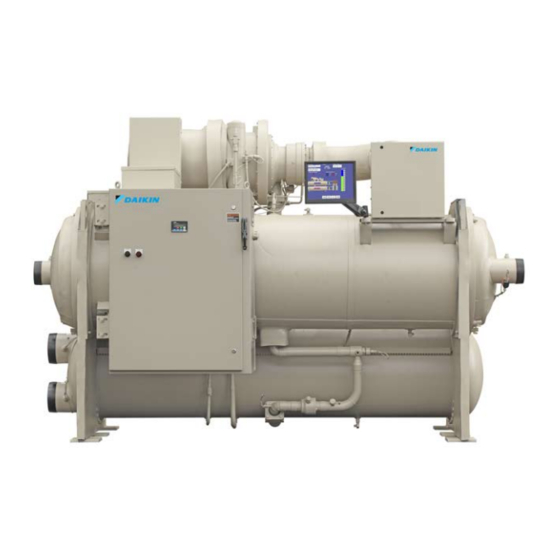
Daikin WSC063 Installation And Maintenance Manual

Daikin WSC063 Installation And Maintenance Manual

Models wsc,wdc,wcc,hsc (includes high voltage 10/11kv wdc/wcc models)

Advertisement

Installation and Maintenance Manual
IM 1044-2
Centrifugal Compressor Water Chillers
Group: Chillers
REV
Part Number: 331374801
0A
Date: August 2012
Models WSC,WDC,WCC,HSC
(Includes High Voltage 10/11kV WDC/WCC models)
© 2013 Daikin Applied

Advertisement

Table of Contents
loading
Need help?

Need help?

Do you have a question about the WSC063 and is the answer not in the manual?

Questions and answers

Praduman
May 26, 2025

Compressor and motor weight required

1 comments:
Mr. Anderson
May 26, 2025

The compressor weight for the Daikin WSC063 is 2000 lb (908 kg). The weight of the motor is not provided in the given information.

This answer is automatically generated

Subscribe to Our Youtube Channel

Summary of Contents for Daikin WSC063

  • Page 1 Installation and Maintenance Manual IM 1044-2 Centrifugal Compressor Water Chillers Group: Chillers Part Number: 331374801 Date: August 2012 Models WSC,WDC,WCC,HSC (Includes High Voltage 10/11kV WDC/WCC models) © 2013 Daikin Applied...
  • Page 2: Table Of Contents

    Replaces: June 2012 ©2012 Daikin. Illustrations and data cover the Daikin product at the time of publication and we reserve the right to make changes in design and construction at anytime without notice. ™® The following are trademarks or registered trademarks of their respective companies: BACnet from ASHRAE; LONMARK, LonTalk, LONWORKS, and the LONMARK logo are managed, granted and used by LONMARK International under a license granted by Echelon Corporation;...
  • Page 3: Introduction

    MicroTech II unit controller (latest version available on www.DaikinApplied.com). All Daikin centrifugal chillers are factory tested prior to shipment and must be initially started at the job site by a factory trained Daikin service technician. Failure to follow this startup procedure can affect the equipment warranty.
  • Page 4: Installation

    Receiving and Handling The unit should be inspected immediately after receipt for possible damage. All Daikin centrifugal water chillers are shipped FOB factory and all claims for handling and shipping damage are the responsibility of the consignee. Insulation corners from the evaporator's rigging hole locations are shipped loose and should be glued in place after the unit is finally placed.
  • Page 5: Location And Mounting

    Figure 2, WDC Major Component Location Oil Sump, Pump, Heaters Motor Terminal Box Rigging Eyes Rigging Eyes Condenser Dual Relief Valves Common Oil Lubrication & Cooler Water Condenser Compressor Connections Control Boxes Notes: Chilled water and condenser connection location can vary. Check markings on unit or consult unit certified drawings for connection locations on specific units.
  • Page 6: Operating/Standby Limits

    Note: Units are shipped with refrigerant and oil valves closed to isolate these fluids for shipment. Valves must remain closed until start-up by the Daikin technician. Nameplates There are several identification nameplates on the chiller: •...
  • Page 7: Low Condenser Water Temperature Operation

    Up to 600 Tons Daikin centrifugal chillers up to 600 Tons are equipped with electronic expansion valves (EXV) and will start and run with entering condenser water temperatures as low as shown in Figure 3 or as calculated from the following equation on which the curves are based.
  • Page 8 Cooling tower fans must continue to operate at 100% capacity at low wet bulb temperatures. As chillers are selected for lower kW per ton, the cooling tower fan motor power becomes a higher percentage of the total peak load chiller power. Daikin's Energy Analyzer program can optimize the chiller/tower operation for specific buildings in specific locales.
  • Page 9: Water Piping

    It is also possible to build up a frequency beat due to the slight difference in the operating rpm of the pump motor and the Daikin centrifugal motor. Daikin encourages the use of 1750/1460 rpm (four-pole) pump motors. Vessel Drains at Start-up Unit vessels are drained of water in the factory and are shipped with the drain plugs in the heads removed and stored in the control panel or with open ball valves in the drain hole.
  • Page 10: Flow Switch

    They also serve to shut down the unit in the event that water flow is interrupted to guard against evaporator freeze-up or excessive discharge pressure. Thermal dispersion flow switches are available from Daikin as a factory-mounted option. It is mounted in an evaporator and condenser water nozzle and factory wired.
  • Page 11 Notes from previous page: 1. A segmented 3-inch paddle (1, 2, and 3 inches) is furnished mounted, plus a 6-inch paddle loose. 2. Flow rates for a 2-inch paddle trimmed to fit the pipe. 3. Flow rates for a 3-inch paddle trimmed to fit the pipe. 4.
  • Page 12 Figure 7, Heat Recovery Schematic HEAT LOAD AUXILIARY HEATER OPEN CIRCUIT RECOVERY TOWER CONDENSER TOWER HEAT RECOVERY CONDENSER CHILLER LEGEND EVAPORATOR TC TEMPERATURE CONTROL POINT PUMP COOLING LOAD Centrifugal Chillers IM 1044-2...
  • Page 13: Field Insulation Guide

    Field Insulation Guide Figure 8, Insulation Requirements, Cooling-only Units IM 1044-2 Centrifugal Chillers...
  • Page 14 Centrifugal Chillers IM 1044-2...
  • Page 15: Physical Data And Weights

    Physical Data and Weights Evaporator The standard insulation of cold surfaces includes the evaporator and non-connection water head, suction piping, compressor inlet, motor housing, and motor coolant outlet line. Insulation is UL recognized (File # E55475). It is 3/4" thick ABS/PVC flexible foam with a skin. The K factor is 0.28 at 75°F.
  • Page 16 Water side design is 150 psi (1034 kPa) on all. Pumpdown To facilitate compressor service, all Daikin centrifugal chillers are designed to permit pumpdown and isolation of the entire refrigerant charge in the unit’s condenser. Dual compressor units and single compressor units equipped with the optional suction shutoff valve can also be pumped down into the evaporator.
  • Page 17: Complete Unit Physical Data

    Charge (1) Shipping Operating Shipping Operating Condenser Size Lbs. (kg) lbs. (kg) lbs. (kg) lbs. (kg) lbs. (kg) WSC063 2009 / 1809 410 (186) 8412 (3816) 8949 (4059) 9612 (4360) 10149 (4604) WSC063 2012 / 1812 539 (244) 9284 (4211)
  • Page 18 Table 6 Unit Weights, Dual Compressor, WDC/WCC Max. Unit Weight Without Starter Max. Unit Weight With Starter (Note 1) Evaporator / Condenser Unit Shipping Operating Shipping Operating Size lbs. (kg) lbs. (kg) lbs. (kg) lbs. (kg) WDC063 2416 / 2416 18673 (8470) 20422 (9263) 21407 (9710)
  • Page 19: Oil Coolers

    POE lubricant. POE must not come into contact with any surface or material that might be harmed by POE, including certain polymers (e.g. PVC/CPVC and polycarbonate piping). Daikin centrifugal chillers have a factory-mounted, water-cooled oil cooler, temperature-controlled water regulating valve and solenoid valve per compressor. WSC/HSC single compressor cooling water connections are located near the compressor and are shown on the specific unit certified drawings.
  • Page 20 Table 9, Freestanding VFD, Cooling Requirements Cooling Cooling Cooling Cooling Water Water Water Water WSC/HSC 063 - 087 Flow, gpm Inlet Temperature, °F 80.0 65.0 55.0 45.0 Outlet Temperature, °F Pressure Drop, ft. 13.0 WSC/HSC 100 - 126 Flow, gpm Inlet Temperature, °F 80.0 65.0...
  • Page 21 Figure 10, Oil Cooler Piping With City Water OIL COOLER SOLENOID VALVE COOLING TOWER STOP WATER VALVE SUPPLY STRAINER COOLING TOWER MAKEUP MAX. 40 DISCHARGE ABOVE MESH HIGHEST POSSIBLE DRAIN VALVE WATER LEVEL OR PLUG OPEN DRAIN Figure 11, Oil Cooler Connections, WSC/HSC Units Compressor Reservoir Controller &...
  • Page 22: Oil Heater

    Oil Heater The oil sump is equipped with an immersion heater that is installed in a tube so that it can be removed without disturbing the oil. Relief Valves As a safety precaution and to meet code requirements, each chiller is equipped with pressure relief valves located on the condenser, evaporator, and oil sump vessel for the purpose of relieving excessive refrigerant pressure (caused by equipment malfunction, fire, etc.) to the atmosphere.
  • Page 23: Electrical

    The formula, and tables derived from it, is contained in ASHRAE Standard 15. Daikin centrifugal units have relief valve settings of 180 psi, 200 psi, and 225 psi, and resultant valve discharge capacities of 68.5 # air/min, 75.5 # air/min, and 84.4 # air/min respectively.
  • Page 24 Note: For installing remote-mounted, free-standing starters see Daikin manual IOMM 1158; for VFDs see Daikin manual IOMM 1159. Note: Do not make final connections to motor terminals until wiring has been checked and approved by a Daikin technician. Under no circumstances should a compressor be brought up to speed unless proper sequence and rotation have been established.
  • Page 25: Installation Instructions For 10/11Kv Motor Units

    Installation Instructions for 10/11kV Motor Units The 10/11 kV motors have additional installation requirements compare to lower voltage motors. Installing Motor Terminal Box For safety and shipping considerations, the chiller is shipped with a disposable protective shield over the motor terminals and a separate field-installed terminal box. CAUTION Exert extreme care when mounting the compressor motor terminal box on the compressor to avoid damage to the motor terminals.
  • Page 26 Insulating Motor Terminals 1. Insulate motor housing around terminals using thermal foam. 2. Thermally insulate the motor terminals. • Use “SCOTCH” Sealant Tape on each end of terminal on glass. • Install full length plus heat shrink tube (see picture to right.) •...
  • Page 27 Connecting Power Leads Power leads are brought in through a removable plate on the top of the terminal box (see Figure 15). The terminal box power connectors are made to the landing points shown in Figure 15captive and attached with a bolt already in the connector. Figure 15, Terminal Box Mounted, Front View Line Power Entry Insulate this area...
  • Page 28 Control Wiring Power leads are brought in through a removable plate on the top of the terminal box (see Figure 15). The terminal box power connectors are made to the landing points shown in Figure 15captive and attached with a bolt already in the connector. Figure 17, Control Wiring Rear Motor Temperature...
  • Page 29: Full Metering Option

    Cable is Belden 9841 or equal (120 OHM characteristic impedence) Control Power Wiring Options The control circuit on the Daikin centrifugal packaged chiller is designed for 115-volts. Control power can be supplied from three different sources: If the unit is supplied with a factory-mounted starter or VFD, the control circuit power supply is factory-wired from a transformer located in the starter or VFD.
  • Page 30 The optional Building Automation System (BAS) interface utilizing the MicroTech II unit controller’s Open Choices feature is field wired and will be set-up by the Daikin startup service technician. The following manuals (available on www.DaikinApplied.com) explain the wiring and mounting procedures: >...
  • Page 31: Field Wiring, Controls & Starters

    If starters are freestanding, then field wiring between the starter and the control panel is required. Minimum wire size for 115 Vac is 12 GA for a maximum length of 50 feet. If greater than 50 feet, refer to Daikin for recommended wire size minimum.
  • Page 32 Figure 19, Field Control Wiring Diagram Centrifugal Chillers IM 1044-2...
  • Page 33 Figure 20, Field Wiring, Remote Starter IM 1044-2 Centrifugal Chillers...
  • Page 34: Multiple Chiller Setup

    Unless otherwise stated in the contract documents, the interconnecting MicroTech II pLAN RS485 multiple chiller wiring between chillers is the responsibility of the installing contractor and should be completed prior to startup. The Daikin startup technician is responsible is to check the wiring and make the appropriate control changes. pLAN Wiring Connect chillers together (pLAN, RS485 wiring) as shown in Figure 21 on the following page.
  • Page 35 Figure 21, Communication Wiring PIGTAIL Chiller A J10 J11 OPDR UNIT CONTROL BLU/WHT WHT/BLU SHIELD Chiller B PORT OPDR J11 PORT UNIT CONTROL BLU/WHT WHT/BLU SHIELD Chiller C (+) (-) J11 Port UNIT CONTROL NOTE: A fourth chiller, Chiller D would be connected to chiller C same as chiller C to chiller B. IM 1044-2 Centrifugal Chillers...
  • Page 36 MicroTech II Operator Interface Touch Screen (OITS) Settings Settings for any type of linked multiple compressor operation must be made to the MicroTech II controller. Settings on a dual compressor unit are made in the factory prior to shipment, but must be verified in the field before startup.
  • Page 37: Prestart System Checklist

    Minimum system load of 80% of machine capacity available for testing    and adjusting controls ...................... (*) Includes heating hot water on heat recovery units. Note: This checklist must be completed and sent to the local Daikin service location two weeks prior to start-up. IM 1044-2 Centrifugal Chillers...
  • Page 38: Commissioning

    This brief section on unit operation is included to assist in commissioning. Complete operating information is contained in Daikin manual OM 1153. During the initial startup of the chiller the Daikin technician will be available to answer any questions and instruct in the proper operating procedures.
  • Page 39 Figure 23, Unit Control Panel ON/OFF Switches UTB1 Unit Terminal Block 110-volt Circuit Breaker pLAN Termination Unit & Control Power Controller Isolation Board Emergency OFF Switch Figure 24, Compressor Control Panel 115-volt Circuit Breaker Latch Relay Heater Relay Terminal Board CTB1 Compressor Relay Bias Block for Starter Display Option Connection...
  • Page 40: Capacity Control System

    Capacity Control System The opening or closing of the inlet vanes controls the quantity of refrigerant entering the impeller thereby controlling the compressor capacity. The vane movement occurs in response to oil flow from the SA or SB 4-way solenoid valves, which in turn, respond to instructions from the unit microprocessor as it senses leaving chilled water temperature.
  • Page 41 Back Seat Port Oil Pump Contactor Relief Valve Oil Pump Capacitor Oil Sump Compressor MicroTech II Solenoid controller Valve Cooling Water Inlet Temperature Control Valve Cooling Water Outlet NOTE: 4-way solenoid valve and vane close switches are located on the compressor suction inlet.
  • Page 42: Surge And Stall

    Figure 28, Vane Control Solenoid Operation, Continued LEGEND OPENING Oil Under Pressure Oil Sump Pressure To Oil Pump Sump #3 Outlet Drain From Piston Section “SB” Energized Section “SA” De-energized #1 Intlet From Oil Pump Discharge CLOSING Piston Drain To Oil Pump Sump #3 Outlet Section “SB”...
  • Page 43 NOTES: 1. Approved oil from two suppliers can be mixed, although they have slightly different viscosity. 2. Lubricant from either supplier can be furnished when ordering by Daikin part number. WARNING This unit contains POE lubricants that must be handled carefully and the proper protective equipment (gloves, eye protection, etc.) must be used when handling POE lubricant.
  • Page 44: Hot Gas Bypass

    When the ambient wet bulb temperature is lower than design, the entering condenser water temperature can be allowed to fall, improving chiller performance. See page 7 for details. Daikin chillers will start with entering condenser water temperature as low as 55°F (42.8°C) providing the chilled water temperature is below the condenser water temperature.
  • Page 45: Maintenance

    It is useful to have an oil analysis at initial startup to provide a benchmark from which to compare future tests. The local Daikin service office can recommend suitable facilities for performing these tests. Table 16 gives the upper limits for metals and moisture in the polyolester lubricants required by Daikin chillers. IM 1044-2 Centrifugal Chillers...
  • Page 46 For TAN above 0.19, change oil, oil filter, and filter-drier and resample at normal interval Changing Oil Filters Daikin chillers are at positive pressure at all times and do not leak contaminated moist air into the refrigerant circuit, thereby eliminating the need for annual oil changes. An annual laboratory oil check is recommended to check overall compressor condition.
  • Page 47 Figure 8. Typical Refrigerant Flow Diagram Connections are not necessarily in correct relative location. Filter is for burnout protection of the refrigerant. IM 1044-2 Centrifugal Chillers...
  • Page 48 If the operator has any reason to suspect that the power system connections have been altered, (phases reversed) the compressor must be jogged to check rotation. For assistance, call the local Daikin service location. Cleaning and Preserving A common cause of service calls and equipment malfunction is dirt.
  • Page 49: Annual Shutdown

    The use of untreated water can result in corrosion, erosion, sliming, scaling or algae formation. It is recommended that the service of a reliable water treatment company be used. Daikin assumes no responsibility for the results of untreated or improperly treated water.
  • Page 50: Repair Of System

    Repair of System Pressure Relief Valve Replacement Current condenser designs use two relief valves separated by a three-way shutoff valve (one set). This three-way valve allows either relief valve to be shut off, but at no time can both be shut off. In the event one of the relief valves are leaking in the two valve set, these procedures must be followed: •...
  • Page 51: Oil Analysis

    Table 1 indicates these parameters. In general Daikin does not recommend changing lubricating oils and filters on a periodic basis. The need to change lubricating oil and filters should be based on a careful consideration of oil analysis, vibration analysis and knowledge of the operating history of the equipment.
  • Page 52 The source of tin may be from bearings. Zinc There is no zinc used in the bearings on Daikin chillers. The source, if any may be from additives in some mineral oils. Lead The source of lead in Daikin centrifugal chillers is the thread sealant compounds used during chiller assembly.
  • Page 53 Periodic oil analysis performed by a reputable laboratory and used in conjunction with compressor vibration analysis and operating log review can be helpful tools in estimating the internal condition of a Daikin chiller. Normal Sample Intervals Daikin International recommends that an oil analysis be performed annually.
  • Page 54: Maintenance Schedule

    Maintenance Schedule Maintenance Check List Item I. Unit · Operational Log · Analyze Operational Log · Refrigerant Leak Test Chiller · Test Relief Valves or Replace II. Compressor · Vibration Test Compressor A. Motor · Meg. Windings (Note 1) · Ampere Balance (within 10% at RLA) ·...
  • Page 55 Daikin's high efficiency heat exchangers have very low design approach temperatures, in the order of one to one and one half degrees F.
  • Page 56: Long Term Storage

    10. Restart by Daikin service technicians will be required and paid to Daikin by the owner or contractor. It is prudent to take photos when the unit is stored to show that the conditions of storage have been met Also document all inspection reports and abnormal conditions found.
  • Page 57: Service Programs

    For further information concerning the many services available, contact your local Daikin service office. Operator Schools Training courses for Centrifugal Maintenance and Operation are held through the year at the Daikin Training Center in Staunton, Virginia. The school duration is three and one-half days and includes instruction on basic refrigeration, MicroTech controllers, enhancing chiller efficiency and reliability, MicroTech troubleshooting, system components, and other related subjects.
  • Page 58 Daikin Training and Development Now that you have made an investment in modern, efficient Daikin equipment, its care should be a high priority. For training information on all Daikin HVAC products, please visit us at www.DaikinApplied.com and click on training, or call 540-248-9646 to speak to the Training Department.

Table of Contents

Save PDF