Daikin WGZ030DW Installation And Maintenance Manual
Water-cooled scroll compressor chiller
Hide thumbs
Also See for WGZ030DW:
- Operating and maintenance manual (88 pages) ,
- Installation, operation and maintenance manual (112 pages) ,
- Installation, operation and maintenance manual (80 pages)
Table of Contents
Advertisement
Water-Cooled Scroll Compressor Chiller
WGZ030DW - WGZ200DW, Packaged Water-Cooled Chillers
WGZ030DA - WGZ200DA, Condenserless Chillers
30 - 200 Tons (105 - 700 kW)
50/60 Hz
R-410A
© 2014 Daikin Applied
Installation and Maintenance Manual
IM 1131-2
Group: Chillers
Part Number: IM1131-2
Date: June 2014
Advertisement
Table of Contents

Related Manuals for Daikin WGZ030DW


Summary of Contents for Daikin WGZ030DW
- Page 1 IM 1131-2 Water-Cooled Scroll Compressor Chiller Group: Chillers Part Number: IM1131-2 Date: June 2014 WGZ030DW - WGZ200DW, Packaged Water-Cooled Chillers WGZ030DA - WGZ200DA, Condenserless Chillers 30 - 200 Tons (105 - 700 kW) 50/60 Hz R-410A © 2014 Daikin Applied...
-
Page 2: Table Of Contents
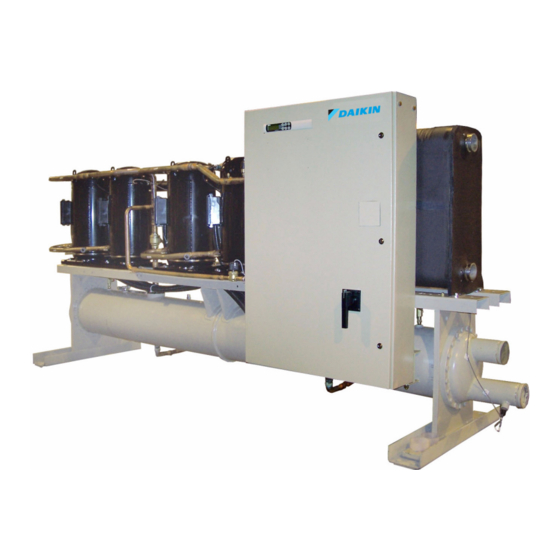
Note: Cover photograph is an WGZ060-D. This manual covers WGZ-D vintage water-cooled scroll chillers. ©2014 Daikin Applied. Illustrations and data cover the Daikin Applied product at the time of publication and we reserve the right to make changes in design and construction at anytime without notice. -
Page 3: Introduction
Nominal Tons Design Vintage General Description Daikin Applied WGZ water chillers are designed for indoor upon arrival. All shipping damage must be reported to the installations and are available with water-cooled condensers carrier and a claim must be filed with the carrier. The unit... -
Page 4: Installation
Installation Installation This space can often be provided through a doorway or other Installation Note: Installation and maintenance are to be performed only opening. by qualified personnel who are familiar with local codes and Moving the Unit regulations, and experienced with this type of equipment. Refer to Lifting/Mounting weights beginning on page CAUTION... -
Page 5: Water Piping
Water Piping Unit Configuration cooled condenser, interconnecting refrigerant piping and a Water Piping control panel with associated sensors and transducers. Models WGZ 030DW to 130DW have two refrigerant circuits, two WGZ 150DW to 200DW have two trio-compressors (total of tandem scroll compressors (total of four), a single two- 6) and a shell-and-tube evaporator. - Page 6 Water Piping Manual or automatic air vent valves at the high points of manufacturer for recommendations). The use of a the system. Drains should be placed at the lowest points strainer will prolong pump life and thus maintain system in the system. performance.
-
Page 7: System Water Volume
Water Piping Figure 3: Typical Evaporator Field Water Piping (WGZ150 - WGZ200) Suction Water Vent Strainer Flow Vibration Gate Eliminator Valved Valve Pressure Gauge Protect All Fi eld Piping Ag ainst Freezing Flow Vibration Flow Balancing Liquid Gate Eliminator Swit ch Valve Drain Valve... -
Page 8: Flow Switch
Leaving Chilled If the optional factory flow switch is not supplied, a flow Water Sensor switch is available from Daikin Applied under part number 01750330. It is a "paddle" type switch and adaptable to any Liquid Circuit #2 pipe size from 1 in. -
Page 9: Glycol Solutions
The condenser water will characteristics similar to water. discharge from the top connection. Failing to arrange the Daikin Applied recommends a minimum concentration of 25% condenser water as stated above will negatively affect the be provided on all glycol applications. Glycol concentrations capacity and efficiency. -
Page 10: Refrigerant Piping
Refrigerant Piping Refrigerant Piping NOTE: On WGZ-DA units (units with remote condensers), the Refrigerant Piping installer is required to record the refrigerant charge by Refrigerant piping, to and from the unit, should be sized and stamping the total charge and the charge per circuit on the installed according to the latest ASHRAE Handbook. - Page 11 Refrigerant Piping Recommended Line Sizing for Field Piping Final design should be based on ASHRAE design standards. Table 1: Equivalent Feet for Fittings Fitting Type 7/8" 1 1/8" 1 3/8" 1 5/8" 2 1/8" 2 5/8" 3 1/8" Elbows 90º Standard 90º...
- Page 12 Refrigerant Piping Table 4: Recommended Horizontal or Downflow Discharge Line Size, R-410A Recom m ended Discharge Line Sizes Conn. Size Unit Model Up to Up to Up to Up to Up to at Unit 50 Equiv. Ft 75 Equiv. Ft 100 Equiv.
- Page 13 Refrigerant Piping Figure 2: Condenser and Compressor on Same Level, Optional Receiver Installation The receiver is bypassed during normal operation. Note: C heck V alve Re lief Va lve Purg e V alve D ischa rge Line P itc h C on denser C heck V alve...
-
Page 14: Pressure Drop Data
Pressure Drop Data Figure 1: WGZ-D Condenser Pressure Drop Curves Pressure Drop Data 1000 Flow Rate (gpm) Table 1: WGZ-D CondenserPressure Drop Data Minimum Flow & Pr. Drop Nominal Flow & Pr. Drop Maximum Flow & Pr. Drop Curve Model Inch-Pound S.I. - Page 15 Pressure Drop Data Figure 2: WGZ-D Evaporator Pressure Drop Curves 1000 Flow Rate (gpm) Table 2: WGZ-D Evaporator Pressure Drop Data Minimum Flow & Pr. Drop Nominal Flow & Pr. Drop Maximum Flow & Pr. Drop Curve Model Inch-Pound S.I. Inch-Pound S.I.
-
Page 16: Dimensions - Packaged
Dimensions - Packaged Figure 1: WGZ030DW - 060DW (Packaged) Dimensions - Packaged IM 1131-2... - Page 17 Dimensions - Packaged Figure 2: WGZ070DW (Packaged) IM 1131-2...
- Page 18 Dimensions - Packaged Figure 3: WGZ080DW - 130DW (Packaged) IM 1131-2...
- Page 19 Dimensions - Packaged Figure 4: WGZ150DW - 200DW (Packaged) IM 1131-2...
-
Page 20: Dimensions - Condenserless
Dimensions - Condenserless Figure 5: WGZ030DA - 060DA (Condenserless) Dimensions - Condenserless IM 1131-2... - Page 21 Dimensions - Condenserless Figure 6: WGZ070DA (Condenserless) IM 1131-2...
- Page 22 Dimensions - Condenserless Figure 7: WGZ080DA - 130DA (Condenserless) IM 1131-2...
- Page 23 Dimensions - Condenserless Figure 8: WGZ150DA - 200DA (Condenserless) (see next page for more dimensions) IM 1131-2...
- Page 24 Dimensions - Condenserless Figure 9: WGZ150DA - 200DA (Condenserless) (continued) IM 1131-2...
-
Page 25: Lifting And Mounting Weights
Table 1: Lifting Weights, WGZ030-060D Packaged LIFTING WEIGHT FOR EACH POINT LBS (KG) MOUNTING LOADS FOR EACH POINT LBS (KG) SHIP WT OPER. WT MODEL LBS (KG) LBS (KG) 2408 2484 WGZ030DW (274) (287) (271) (259) (283) (296) (280) (268) (1092) - Page 26 Lifting and Mounting Weights Figure 3: Lifting Locations, WGZ150-200D Packaged L4/M4 EVAP. OUTLET L3/M3 EVAP. INLET WATER CONNECTIONS CONTROL BOX L2/M2 L1/M1 Table 3: Lifting Weights, WGZ150-200D Packaged LIFTING WEIGHT FOR EACH POINT LBS (KG) MOUNTING LOADS FOR EACH POINT LBS (KG) SHIP WT OPER.
- Page 27 Lifting and Mounting Weights Figure 5: Lifting Locations, WGZ070-130D Condenserless 21.0 95.0 21.0 2413 CIRCUIT 2 CIRCUIT 1 EVAP. WATER 30.0 CONNECTIONS CONTROL BOX *333611611003* CERT. WGZ070-130D, LESS COND ISOLATOR HOLES IN THE BOTTOM OF THE BASE Table 5: Lifting Weights, WGZ070-130D Condenserless LIFTING WEIGHT FOR EACH POINT LBS (KG) MOUNTING LOADS FOR EACH POINT LBS (KG) SHIP WT...
-
Page 28: Vibration Isolators
332325501 332325505 Table 8: Vibration Isolator Mounting Locations (Packaged Chillers) Unit Spring-Flex Mountings R-I-S Mountings Size ID-900 ID-900 ID-900 ID-900 RP-3 RP-3 RP-3 RP-3 WGZ030DW Green Green Green Green Gray Gray Gray Gray ID-900 ID-900 ID-900 ID-900 RP-3 RP-3 RP-3... - Page 29 Vibration Isolators Table 9: Vibration Isolator Mounting Locations (Packaged Chillers), continued Unit Spring-Flex Mountings R-I-S Mountings Size ID-1800 ID-1800 ID-1800 ID-2400 RP-4 RP-4 RP-4 RP-4 WGZ115DW Green Green Green Gray Brick Red Brick Red Brick Red Brick Red ID-1800 ID-1800 ID-1800 ID-2400 RP-4...
-
Page 30: Physical Data - Packaged Units
Physical Data - Packaged Units Table 20: Physical Data - WGZ030D - WGZ055D Physical Data - Packaged Units WGZ UNIT SIZE Unit capacity @ AHRI tons, (kW) (Note 1) 30.0 (105.5) 34.6 (121.7) 40.7 (143.1) 45.5 (160.0) 51.4 (180.7) 56.4 (198.3) No. - Page 31 Physical Data - Packaged Units Table 21: Physical Data - WGZ060D - WGZ100D W GZ UNIT SIZE Unit capacity @ A HRI tons, (kW) (Note 1) 60.5 (212.7) 70.2 (246.8) 78.3 (275.3) 87.1 (306.3) 97.8 (343.9) No. Circuits COMPRESSORS Nominal Tons 15/20 15/20 20/26...
- Page 32 Physical Data - Packaged Units Table 22: Physical Data - WGZ115D - WGZ200D WGZ UNIT SIZE Unit capacity @ AHRI tons, (kW) (Note 1) 112.9 (397.0) 126.7 (445.5) 148.2 (521.1) 169.3 (595.3) 188.1 (661.4) No. Circuits COMPRESSORS Nominal Tons 26/30 26/30 Number Per Circuit CAPACITY REDUCTION STEPS - PERCENT OF COMPRESSOR DISPLACEMENT...
-
Page 33: Physical Data - Units Less Condenser
Physical Data - Units Less Condenser Table 23: Physical Data - WGZ030D - AGZ055D Physical Data - Units Less Condenser WGZ UNIT SIZE Tons (kW) (at 44°F LWT/125°F SDT) 26.9 (94.6) 31.2 (109.7) 36.2 (127.3) 40.3 (141.7) 46.3 (162.8) 50.6 (177.9) No. - Page 34 Physical Data - Units Less Condenser Table 25: Physical Data - WGZ115D - AGZ200D WGZ UNIT SIZE Tons (kW) (at 44°F LWT/125°F SDT) 101.9 (358.3) 115.1 (404.7) 133.1 (468.0) 153.7 (540.4) 174.3 (612.8) No. Circuits COMPRESSORS Nominal Tons 26/30 26/30 Number per Circuit CAPACITY REDUCTION STEPS - PERCENT OF COMPRESSOR DISPLACEMENT Staging, Circuit #1 in Lead...
-
Page 35: Electrical Data
Electrical Data Electrical Notes Notes for "Field Wiring Data" Electrical Data Requires a single disconnect to supply electrical power Notes for "Electrical Data Single Point" Power: to the unit. This power supply must either be fused or use If a separate 115V power supply is used for the control an HACR type circuit breaker. - Page 36 Electrical Data Panel Ratings Units without Supplemental Overloads Standard Panel WGZ-D Model Size Voltage WGZ 030-040 WGZ 045-090 WGZ 100-200 208-230 Optional High Short Circuit Current Rating Panel Options, Single-Point Voltage Power Connection Only 208-230 Not Available Units with Supplemental Overloads Standard Panel WGZ-D Model Size Voltage...
- Page 37 Electrical Data Figure 28: Field Wiring Diagram (Packaged Units) IM 1131-2...
- Page 38 Electrical Data Figure 29: Field Wiring Diagram (Units less condenser) IM 1131-2...
- Page 39 Electrical Data Table 26: Compressor Amp Draw (with and without optional external overloads) Rated Load Am ps Per Com pressor Rated Load Am ps Per Com pressor Locked Rotor Amps Unit w /o Optional External Overloads Unit w ith Optional External Overloads Across-The-Line Starting Unit Volts...
- Page 40 Electrical Data Table 27: Compressor Amp Draw (with and without optional external overloads) Rated Load Amps Per Compressor Rated Load Amps Per Compressor Locked Rotor Am ps Unit w /o Optional External Overloads Unit w ith Optional External Overloads Across-The-Line Starting Unit Volts Circuit 1...
- Page 41 Electrical Data Table 28: Wire Sizing Amps - Single Point without optional External Overloads M ax M odel Field Wire Field Hub. Model Field Wire Field Hub. Voltage M CA Fuse Voltage Fuse Size Size Size Size Wire GA Size Wire GA Size 208V...
- Page 42 Electrical Data Table 29: Wire Sizing Amps - Single Point with optional External Overloads Model Field Wire Field Hub. Model Field Wire Field Hub. Voltage Voltage Size Wire GA Size Fuse Size Wire GA Size Fuse 208V 3 AWG 1.00 208V 250 MCM 2.00...
- Page 43 Electrical Data Table 30: Wire Sizing Amps - Multi-Point without optional External Overloads Field Wire Field Hub. Field Wire Field Hub. Model Cir. 1 Cir. 2 Voltage Fuse Fuse Size Wire GA Size Wire GA Size Size Size 208V 4 AWG 1.00 4 AWG 1.00...
- Page 44 Electrical Data Table 31: Wire Sizing Amps - Multi-Point without optional External Overloads (continued) Model Cir. 1 Cir. 2 Field Wire Field Hub. Field Wire Field Hub. Voltage Fuse Fuse Size Size Size Wire GA Size Wire GA Size 208V 3/0 AWG 2.00 3/0 AWG...
- Page 45 Electrical Data Table 32: Wire Sizing Amps - Multi-Point with optional External Overloads Field Wire Field Hub. Field Wire Field Hub. Model Cir. 1 Cir. 2 Voltage Fuse Fuse Size Wire GA Size Wire GA Size Size Size 208V 8 AWG 0.50 8 AWG 0.50...
- Page 46 Electrical Data Table 33: Wire Sizing Amps - Multi-Point with optional External Overloads (continued) Model Cir. 1 Cir. 2 Field Wire Field Hub. Field Wire Field Hub. Voltage Fuse Fuse Size Size Size Wire GA Size Wire GA Size 208V 1/0 AWG 1.50 1/0 AWG...
- Page 47 Electrical Data Table 34: Connection Sizing - Single Point without optional External Overloads Model Voltage Pow er Block [2] Disconnect Sw itch [2] Model Voltage Pow er Block [2] Disconnect Sw itch [2] Size Size Size Lug Range Size Lug Range Size Size Size...
- Page 48 Electrical Data Table 35: Connection Sizing - Single Point with optional External Overloads Model Voltage Pow er Block [2] Disconnect Sw itch [2] Model Voltage Pow er Block [2] Disconnect Sw itch [2] Size Size Size Lug Range Size Lug Range Size Size Size...
- Page 49 Electrical Data Table 36: Connection Sizing - Multi-Point without optional External Overloads Model Voltage Cir #1 Power Block [2] Cir #1 Disconnect Sw [2] Cir #2 Power Block [2] Cir #2 Disconnect Sw [2] Size Size Size Lug Range Size Lug Range Size Lug Range...
- Page 50 Electrical Data Table 37: Connection Sizing - Multi-Point without optional External Overloads (continued) Model Voltage Cir #1 Power Block [2] Cir #1 Disconnect Sw [2] Cir #2 Power Block [2] Cir #2 Disconnect Sw [2] Size Size Size Lug Range Size Lug Range Size...
- Page 51 Electrical Data Table 38: Connection Sizing - Multi-Point with optional External Overloads Model Voltage Cir #1 Power Block [2] Cir #1 Disconnect Sw [2] Cir #2 Power Block [2] Cir #2 Disconnect Sw [2] Size Size Size Lug Range Size Lug Range Size Lug Range...
- Page 52 Electrical Data Table 39: Connection Sizing - Multi-Point with optional External Overloads (continued) Model Voltage Cir #1 Power Block [2] Cir #1 Disconnect Sw [2] Cir #2 Power Block [2] Cir #2 Disconnect Sw [2] Size Size Size Lug Range Size Lug Range Size...
-
Page 53: Start-Up And Shutdown
Check water pressure drop across evaporator and with the unit and after completion should be returned to condenser, and see that water flow is correct (beginning the Daikin Applied service through your sales on page 17) per the design flow rates. representative. - Page 54 Start-Up and Shutdown Start-up after Temporary Shutdown Open the manual liquid line shutoff valves. Start the water pumps. Check circuit breakers. They must be in the "off" position. With the control system switch S1 in the "on" position, move the pumpdown switches PS1 and PS2 to the "auto Check to see that the pumpdown switches PS1 and PS2 pumpdown"...
-
Page 55: System Maintenance
A pressure tap has been provided on the liquid line to the atmosphere to prevent this problem. For more details on downstream of the filter-drier and solenoid valve but before acceptable oil types, contact your Daikin Applied service the expansion valve. An accurate subcooled liquid pressure representative. -
Page 56: Crankcase Heaters
System Maintenance Oil can be added to the compressor through the oil fill hole in Phase/Voltage Monitor (Optional) the crankcase. Special equipment is required to add oil and the The phase/voltage monitor is a device that provides protection work should be done by qualified refrigeration technicians against three-phase electrical motor loss due to power failure with the proper training and equipment. -
Page 57: Maintenance Schedule
Maintenance Schedule Table 40: Periodic Maintenance Schedule Maintenance Schedule I. Compressor A. Performance evaluation (log & analysis) * B. Motor • Meg. windings • Ampere balance (within 10%) • Terminal check (tight connections, porcelain clean) • Motor cooling (check temperature) C. -
Page 58: System Service
System Service the screw clockwise (when viewed from the adjustment screw System Service System Service end) to increase the superheat and counterclockwise to reduce DANGER superheat. Allow time for system rebalance after each superheat adjustment. Service on this equipment is to be performed only by qualified refrigeration personnel. -
Page 59: Troubleshooting Chart
Troubleshooting Chart Table 41: Troubleshooting Chart Troubleshooting Chart PROBLEM POSSIBLE CAUSES POSSIBLE CORRECTIVE STEPS Main sw itch, circuit breakers open. Close sw itch Check electrical circuits and motor w inding for shorts or grounds. Fuse blow n. Investigate for possible overloading. Replace fuse or reset breakers after fault is corrected. -
Page 60: Warranty Registration Form (Scroll)
P.O Box 2510 Staunton Warranty Department w ithin te n (10) days of start-up in order to comply Staunton, VA 24402-2510 w ith the terms of "Daikin Limited Product Warranty". Check, Test and Commissioning for Scroll Product (AGZ, ACZ, W GZ, TGZ) - Page 61 Warranty Registration Form (Scroll) M. Are all service and liquid line valves open? N. Have all shipping hold down plates been removed? O. Has a flow switch been installed per the IM bulletin? P. Has the chill water circuit been cleaned, flushed, and water treatment confirmed? Q.
- Page 62 Warranty Registration Form (Scroll) MICROTECH STATUS CHECK-Each Reading Must be Verified with Field Provided Instruments of Known Accuracy? MicroTech Verification C. Water Temperatures: Leaving Evaporator ……………………………… °F (°C) °F (°C) Entering Evaporator ……………………………… °F (°C) °F (°C) Entering Condenser ……………………………… °F (°C) °F (°C) Leaving Condenser...
- Page 63 Warranty Registration Form (Scroll) VI. CONTROL CHECK AND SETPOINT VERIFICATION/STANDARD UNIT SETPOINT MICROTECH SETPOINTS MICROTECH STANDARD A. Leaving Evaporator ………………………………………………………………….. °F (°C) °F (°C) B. Reset Leaving ……………………………………………………………………… °F (°C) °F (°C) C. Reset Signa ..………………………………………………………………………… D. Reset Option…………………………………………………………………………. E. Maximum Chilled Water Reset …………………………………………………… °F (°C) °F (°C) F.
- Page 64 Daikin Applied Training and Development Now that you have made an investment in modern, efficient Daikin Applied equipment, its care should be a high priority. For training information on all Daikin Applied HVAC products, visit us at www.DaikinApplied.com and click on Training, or call 540-248-9646 to speak to the Training Department.
Need help?
Do you have a question about the WGZ030DW and is the answer not in the manual?
Questions and answers