Table of Contents
Advertisement
Quick Links
Advertisement
Table of Contents

Related Manuals for Daikin MAGNITUDE WMT


Summary of Contents for Daikin MAGNITUDE WMT
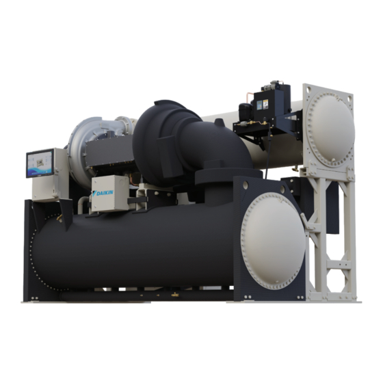
- Page 1 INSTALLATION, OPERATION & MAINTENANCE IOM 1297 DECEMBER 2023 MAGNITUDE ® MAGNETIC BEARING OIL-FREE CENTRIFUGAL CHILLERS • MODEL WMT • 350 TO 600 TONS (1200 TO 2200 kW) • R-1233zd(E) REFRIGERANT LEARN MORE AT DAIKINAPPLIED.COM ©2023 DAIKIN APPLIED | (800) 432.1342...
-
Page 2: Table Of Contents
©2023 Daikin Applied, Minneapolis, MN. All rights reserved throughout the world.This document contains the most current product information as of this printing. Daikin Applied Americas Inc. has the right to change the information, design, and construction of the product represented within the document without prior notice. -
Page 3: Introduction
Polyolester Oil, commonly known as POE oil is a synthetic oil used in many refrigeration systems, and may be present in this Daikin Applied product. POE oil, if ever in contact with PVC/ CPVC, will coat the inside wall of PVC/CPVC pipe causing environmental stress fractures. -
Page 4: General Description
Necessary equipment protection and operating controls are included. No . Description All Daikin Applied centrifugal chillers must be commissioned by a W = Water-Cooled factory-trained Daikin Applied service technician. Failure to follow M = Magnitude Magnetic Bearing Chiller this startup procedure can affect the equipment warranty. -
Page 5: Installation
Table 1: Operating/Standby Limits The unit should be inspected immediately after receipt for Acceptable Temperatures (WMT) R-1233zd(E) possible damage. All Daikin Applied centrifugal water chillers are Min Temp Max Temp shipped FOB factory and all claims for handling and shipping... -
Page 6: Clearance
INSTALLATION Clearance Daikin Applied is not a licensed nor certified rigging specialist. Therefore it is the customer’s responsibility to consult a certified The unit must be placed in an area that allows for adequate rigging contractor to rig, lift, and move components and clearance around the unit. -
Page 7: Transit And Temporary Storage
Daikin Applied will not be responsible for any refrigerant loss during the storage time, for repairs to... -
Page 8: Water Piping
Daikin Applied product. POE oil, if ever in contact with PVC/ water pressure drop. CPVC, will coat the inside wall of PVC/CPVC pipe causing NOTICE environmental stress fractures. -
Page 9: Vessel Drains At Startup
Strainers must be used to protect the chiller and prevent condensation from forming. Insulation should cover: systems from water-borne debris. Daikin Applied will not be responsible for any water-borne debris damage or water side • The evaporator barrel, tube sheet, and waterboxes damage to the chiller heat exchangers due to improperly treated •... -
Page 10: Retrofit Knockdown
INSTALLATION Retrofit Knockdown Magnitude WMT chillers are relatively easy to disassemble due to the small compressor size, simplified refrigerant piping, and the absence of a lubrication system with its attendant components and piping. Various knockdown arrangements are available as options and are ideal for retrofit applications with tight installation clearances. - Page 11 • Compressors and vessels receive an inert gas holding charge • Site re-assembly must be supervised or completed by Daikin Applied service personnel • All free piping ends are capped • Ideal for retrofit applications where installation access is • Suction and discharge lines have bolt-on flanges and, if...
- Page 12 INSTALLATION Figure 8: Partial Disassembly - Economizer 500T Figure 9: Partial Disassembly DAIKIN APPLIED MAGNITUDE WMT CHILLER...
- Page 13 INSTALLATION Figure 10: Partial Disassembly Figure 11: Partial Disassembly WWW.DAIKINAPPLIED.COM IOM 1297...
-
Page 14: Physical Data
Component Weights NOTICE Drawings, dimensional values, and other information may Component Dry Weight change depending on options or configurations selected. Refer to the as-built submittal drawings provided by a Daikin Applied sales representative for configuration-specific details. Compressor 5,318 2412 Compressor... -
Page 15: Electrical
Use the electrical data either on the VFD data plate or supplied with the chiller performance rating sheet – obtained from the Daikin Applied sales office – for generator sizing purposes. The referenced data will show the RLA and LRA. -
Page 16: Wiring Schematics
SEE SHEET 03 FOR OPT. RAPID RESTORE WIRING BY BRAIDED GROUND STRAP REVISION CHANGE DESCRIPTION THE CONTENTS OF THIS MATERIAL ARE CONFIDENTIAL AND PROPRIETARY TO DAIKIN APPLIED. ANY UNAUTHORIZED USE, REPRODUCTION, DISCLOSURE OR TRANSFER IS STRICTLY INITIAL RELEASE PROHIBITED. IF FURNISHED WITH A PROPOSAL, RECIPIENT MAY USE THIS MATERIAL SOLELY... - Page 17 ELECTRICAL COMPR BOX 04-5-D COMM TO UE02 PC RESET ETHERNET J25 BMS2 J26 FBus2 UC01 FIELD BUS CARD BMS CARD LON CARD OPT. LONMARK WIRING EVAP GPM & COND GPM SW1 (UNIT SWITCH) CUSTOMER SUPPLIED +24V SENSOR OPTIONS EEFS CEFS VALVE CONTROLLER ECBL-BLK#3 INPUT+...
- Page 18 +24V REVISION CHANGE DESCRIPTION DESCRIPTIO THE CONTENTS OF THIS MATERIAL ARE CONFIDENTIAL AND PROPRIETARY TO DAIKIN APPLIED. ANY UNAUTHORIZED USE, REPRODUCTION, DISCLOSURE OR TRANSFER IS STRICTLY INITIAL RELEASE PROHIBITED. IF FURNISHED WITH A PROPOSAL, RECIPIENT MAY USE THIS MATERIAL SOLELY LOCATION TO EVALUATE SUCH PROPOSAL.
- Page 19 ELECTRICAL Figure 16: Power Cable Configuration (Standard 24V Power) PWR1 - BLK#1 +24V +24V CONFIGURATION PWR1 - BLK#2 PWR1 - GRN RAPID RESTORE OPTION Figure 17: Power Cable Configuration (RapidRestore Option) PWR1 - BLK#2 PWR1 - BLK#1 100-240VAC; 50-60Hz; MIN UPS OUTPUT 240VA; 2A PWR1 - BLK#2 POWER SOURCE SUPPLIED BY OTHERS +24V...
- Page 20 04-3-B -DO0 REVISION CHANGE DESCRIPTI THE CONTENTS OF THIS MATERIAL ARE CONFIDENTIAL AND PROPRIETARY TO DAIKIN APPLIED. ANY UNAUTHORIZED USE, REPRODUCTION, DISCLOSURE OR TRANSFER IS STRICTLY INITIAL RELEASE PROHIBITED. IF FURNISHED WITH A PROPOSAL, RECIPIENT MAY USE THIS MATERIAL SOLELY TO EVALUATE SUCH PROPOSAL.
- Page 21 ELECTRICAL SEE SHEET 05 SEE SHEET 07 VFD PWRBOX SEE IGVDRV FROM UNIT BOX DO NOT CONNECT SHIELD WIRE TO PE HERE. SEE VFD POWERBOX TERMINALS. ETHERNET pLAN J25 BMS2 J26 FBus2 CC01 FIELD BUS CARD BMS CARD CMPR BOX TERMINALS SCP2 DCP2...
- Page 22 HFK1 CNT1 REVISION CHANGE DESCRIPTION THE CONTENTS OF THIS MATERIAL ARE CONFIDENTIAL AND PROPRIETARY TO DAIKIN APPLIED. ANY UNAUTHORIZED USE, REPRODUCTION, DISCLOSURE OR TRANSFER IS STRICTLY INITIAL RELEASE PROHIBITED. IF FURNISHED WITH A PROPOSAL, RECIPIENT MAY USE THIS MATERIAL SOLELY TO EVALUATE SUCH PROPOSAL.
- Page 23 ELECTRICAL TO VFD POWERBOX (380-480V ONLY) 07-8-D 07-8-D 07-8-D BL - BLK#1 07-5-B BL - BLK#2 07-5-B BL - GRN 07-5-B TO VFD POWERBOX (380-480V ONLY) 07-8-D 07-8-D 07-8-D OUTPUT INPUT DESCRIPTION: WMT500-800T UNIT SCHEM SIZE SHEET PART NUMBER LOCATION ECO NUMBER DATE 335928000...
- Page 24 ISOLATED GROUND REVISION CHANGE DESCRIPTION THE CONTENTS OF THIS MATERIAL ARE CONFIDENTIAL AND PROPRIETARY TO DAIKIN APPLIED. ANY UNAUTHORIZED USE, REPRODUCTION, DISCLOSURE OR TRANSFER IS STRICTLY INITIAL RELEASE PROHIBITED. IF FURNISHED WITH A PROPOSAL, RECIPIENT MAY USE THIS MATERIAL SOLELY TO EVALUATE SUCH PROPOSAL.
- Page 25 ELECTRICAL EMI FILTER OPT. MOTOR MTR1 FU06 FU14 FU08 FU07 FU15 FU09 +175 FU10 -175 FU12 FU11 FU13 COMM 07-7-B FU02 FU03 120A UP TO 4 FANS FANx FU04 120B FU05 120C 120N FU01 GE DESCRIPTION DESCRIPTION: WMT500-800T UNIT SCHEM SHEET SIZE PART NUMBER...
-
Page 26: Operation
During selected external control source, it will start the evaporator the initial startup of the chiller, the Daikin Applied technician will pump and check for flow and chiller load. be available to answer any questions and instruct the proper operating procedures. -
Page 27: Unit Enabling/Disabling And Overrides
Contact the chiller over a BAS network. To enable the chiller and its your local Daikin Applied sales office if your application requires a compressors, the Manual Button needs to be closed in the condenser entering water temperature lower than 40°F (4.4°C). -
Page 28: Condenser Water Temperature Control
Contact your local Daikin Applied representative for more 2 . Two-Way Valve Operation information on this application. Another condenser control method is to use a modulating two-way control valve located on the outlet connection of the condenser. -
Page 29: Human Machine Interface
OPERATION Human Machine Interface Home View Screen A single HMI is used per unit. The HMI panel is mounted on a Figure 21: Home View Screen movable arm to allow placement in a convenient position for the operator. The HMI is used for viewing unit information and entering setpoints into the control system. - Page 30 This red ALARM button will appear on all screens in the case of an alarm. See Figure 25 for an example of an active alarm alert. For more information on alarms, see page 41 . Figure 25: Active Alarm Icon DAIKIN APPLIED MAGNITUDE WMT CHILLER...
- Page 31 OPERATION Figure 28: Evaporator Information Figure 30: Condenser Information Figure 29: Compressor Details Figure 31: Expansion Valve Information Figure 32: Cooling Tower Information The Compressor State Information on the right side of the screen is a compilation of events the chiller sequences through at startup.
-
Page 32: Settings Screen
4 . TOWER - selects the method of controlling the cooling • T = Technician Level (The password number for tower and sets the parameters for fan staging/VFD. technician level is only provided to Daikin Applied 5 . VALVE - sets the parameters for operation of the expansion technicians.) valve. - Page 33 4-20 mA (4 mA=- Setpoints that have a technician level password (T) should None, 20 mA=Max only be changed by a Daikin Applied technician. Contact a as set by Max Daikin Applied service representative for more information. Reset Delta T)
- Page 34 Pump #2 Only - use Load Pump #2 Pump only specified pump Balance Only, Pump Pump #1 Prima- #1 Primary, ry and Pump #2 Pump #2 Primary - if primary Primary pump fails, other pump is used Compressor DAIKIN APPLIED MAGNITUDE WMT CHILLER...
- Page 35 OPERATION Figure 37: Settings View - Tower Description Default Range Comments Max pressure ratio for which a 1.7 for Tandem lead-lag start will be WMT092 Pressure 1-3.5 performed. A higher 2.0 for Ratio Limit pressure ratio will WMT106 trigger a tandem start .
- Page 36 • (E)nable threshold = 90 / N stages • (D)isable threshold = 20 3 . Lift, Auto: Tower control is reactive to the delta between DAIKIN APPLIED MAGNITUDE WMT CHILLER...
- Page 37 OPERATION • For 2 stages: Figure 40: Settings View - Valves • 1 on E*1 TCLO and tower valve > 90%, 2 on E*2 TCLO and tower valve = 100% • 2 off D*2 TCLO, 1 off D*1 TCLO • For 3 3 stages: •...
- Page 38 38.0°F occurs when unit is Protect off and chiller senses need to provide flow to address a chiller limit alarm. Glycol Enables Glycol mode Glycol en- Off, On to allow lower tem- abled perature setpoints. DAIKIN APPLIED MAGNITUDE WMT CHILLER...
- Page 39 Table 13: Commission Setpoint Settings are the controllers’ software identification. These numbers may Description Default Range Comments be required by Daikin Applied to answer questions about unit Compressor operation or to assist in possible future upgrades of software. 98% indicates vanes Maximum 90-110%...
- Page 40 Figure 46: Trend History Screen other functions including manual capacity control. While this override is in effect, chiller capacity is continuously adjusted to keep the % RLA near the limit value. Figure 45: Settings View - Updater DAIKIN APPLIED MAGNITUDE WMT CHILLER...
-
Page 41: Alarms
OPERATION Alarms Clearing an Alarm There are two different indicators that the chiller will generate The Alarm information is accessed by touching the ALARM icon when conditions arise that are affecting the chiller operations. at the bottom of the HMI and then the Active or History tabs at the Warnings are indicated in yellow on the HMI and communicate top of the screen. - Page 42 (Trend.csv and AlarmHistory.csv, ) must be sent together to display “download complete” once the history files have Daikin Applied. Any other file formats are NOT accepted. been successfully transferred to the USB drive. 5 . Repeat this process for each desired day of history. Each day must be downloaded individually.
- Page 43 OPERATION Table 15: Critical Alarms Screen Text Trigger Condition Screen Text Trigger Condition Motor Winding All Motor Winding Temperature Sensors are detect- Temperature Evaporator Pressure (or lowest Suction Pressure ed as bad or disconnected. Sensor Fault if Evaporator Pressure Transducer is detected as bad or disconnected) is less than Low Evap- High Suction Low Evapora-...
-
Page 44: Controller Inputs & Outputs
4 to 20 mA Chiller 0 to 100% Level Sensor Current Reset of 4 to 20 mA Leaving Water Field 0 to 100% Current Temperature 4 to 20 mA Demand Limit Field 0 to 100% Current DAIKIN APPLIED MAGNITUDE WMT CHILLER... -
Page 45: Building Automation Systems
NTC Thermistor -40 to 150°C interface installation manual was shipped with the unit. If 25°C ture 5 necessary, contact your local Daikin Applied sales office for a replacement manual or obtain one from www.DaikinApplied.com . Motor Wind- 10k @ ing Tempera- NTC Thermistor -40 to 150°C... -
Page 46: Startup And Maintenance
Figure 49: Flow Switch Details Dyes used for refrigerant leak detection are not tested or recommended for use in Daikin Aplied chillers. Use of these products may damage and/or degrade the performance of the equipment and will void the manufacturer warranty... - Page 47 STARTUP AND MAINTENANCE Wiring Figure 50: Mount in Direction of Flow Refer to wiring diagram in the unit control panel. Either AC or DC is used to power the flow switch. The unit controller’s digital input is a DC signal which is supplied through the switch output of the flow switch for flow indication.
- Page 48 In Step 3, the ‘Teach’ function re-adjusted the flow switch SP while flow was at the minimum desired operating flow. The chiller will not operate at this flow because the flow switch is OPEN after performing the ‘Teach’ function. The benefit of the ‘Teach’ DAIKIN APPLIED MAGNITUDE WMT CHILLER...
-
Page 49: Chiller Maintenance
STARTUP AND MAINTENANCE Step 5: Once the SP is set, it is recommended that the sensor be Figure 56: Display for Flow Above Range locked to avoid inadvertent readjustment. This can be performed by pressing both the ‘+’ and ‘-’ buttons simultaneously for 10 seconds. -
Page 50: Seasonal Shutdown
Special tube and water head material may be required to reduce damage from corrosion. Daikin Applied is not responsible II . MicroTech Controls for damage or faulty operation from untreated or improperly Check for proper treated water. -
Page 51: Harmonic Filter Evaluation
STARTUP AND MAINTENANCE Harmonic Filter Evaluation If the optional harmonic filter is provided with the chiller, measuring the current in each of the three phases of the capacitor circuit may help determine the condition of the capacitors. If the input phase currents are within a 5% match to each other and approximately 30% of filter current rating, the Clean and Leak Test capacitors can be assumed to be in good working condition. -
Page 52: R-1233Zd(E) Temperature And Pressure Chart
55 .26 -0.27 57 .33 0 .35 59 .45 0 .99 61 .62 1 .64 63 .83 2 .33 66 .09 3 .03 68 .39 3 .76 70 .75 4 .50 73 .16 5 .28 DAIKIN APPLIED MAGNITUDE WMT CHILLER... -
Page 53: Appendix
Document Attached: Final Order Acknowledgement Notes: The most common problems delaying start-up and affecting unit reliability are: Field installed compressor motor power supply leads too small. Questions: Contact the local Daikin Applied sales representative. State size, number and type of conductors and conduits installed:... - Page 54 APPENDIx DAIKIN APPLIED MAGNITUDE WMT CHILLER...
-
Page 55: Limited Product Warranty
(collectively “Owner”) that, subject to the exclusions set forth below Company, at its option, will repair or replace defective parts in the event any product manufactured by Company, including products sold under the brand name Daikin and used in the United States or Canada, proves defective in material or workmanship within twelve (12) months from initial startup or eighteen (18) months from the date shipped by Company, whichever occurs first. - Page 56 1 - 8 0 0 - 4 3 2 - 1 3 4 2 | 7 6 3 - 5 5 3 - 5 3 3 0 LEARN MORE AT DAIKINAPPLIED.COM PART NUMBER: IOM1297 © 2023 DAIKIN APPLIED | (800) 432.1342 | WWW.DAIKINAPPLIED.COM...
Need help?
Do you have a question about the MAGNITUDE WMT and is the answer not in the manual?
Questions and answers