Eaton 93PR User And Installation Manual
500 kw
Hide thumbs
Also See for 93PR:
- User and installation manual (98 pages) ,
- Installation and operation manual (143 pages) ,
- Installation and operation manual (122 pages)
Table of Contents
Advertisement
Quick Links
Advertisement
Table of Contents

Related Manuals for Eaton 93PR


Summary of Contents for Eaton 93PR
- Page 1 Eaton 93PR UPS 500 kW User's and Installation Guide...
- Page 3 Eaton 93PR UPS 500 kVA User's and Installation Guide...
- Page 4 The contents of this manual are the copyright of the publisher and may not be reproduced (even extracts) without the written approval of Eaton Corporation. Every care has been taken to ensure the accuracy of the information contained in this manual,...
-
Page 5: Table Of Contents
Environmental and Installation Considerations ..................19 3.2.2. UPS System Power Wiring Preparation ....................25 3.2.3. UPS System Interface Wiring Preparation ................... 29 3.3. Inspecting and Unpacking the UPS Cabinets ....................30 Eaton 93PR 500 kW UPS User's and Installation Guide... - Page 6 Relay Output Interface Connections ....................40 4.4.4. Mini-slot Interface Connections ......................40 4.4.5. Installing Signal Interface Connections In Parallel System ..............41 4.5. Wiring Parallel 93PR UPS Systems ........................41 4.5.1. Power Wiring Overview........................41 4.5.2. Control Signals Overview ........................44 4.5.3.
- Page 7 8.3. UPS System Output ............................75 8.4. Battery Specification ............................76 8.5. UPS Environmental Specifications ........................77 Chapter 9 WARRANTY ................................. 78 Chapter 10 INSTALLATION CHECKLIST ..........................79 Chapter 11 APPENDIX A: USER SETTINGS........................80 Eaton 93PR 500 kW UPS User's and Installation Guide...
- Page 8 Figure 2-1: Eaton 93PR UPS ..............................7 Figure 2-2: Position Indication ..............................8 Figure 2-3: 93PR 500kW UPS Wiring Diagram ........................10 Figure 2-4: Path of current through the UPS in Double Conversion Mode ................12 Figure 2-5: Path of current through the UPS in Energy Saver System ..................13 Figure 2-6: Path of current through the UPS in Battery Mode ....................14...
- Page 9 Figure 6-10: Maintenance Bypass Mode ..........................68 Figure 6-11: Double Conversion Mode ..........................69 Figure 7-1: WEEE Symbol ..............................72 Figure 7-2: Recycling Batteries Symbol ..........................72 Eaton 93PR 500 kW UPS User's and Installation Guide...
- Page 10 Table 8-3: UPS System Output .............................. 75 Table 8-4: Battery Specification ..............................76 Table 8-5: UPS environmental specifications ......................... 77 Table 11-1: User Settings ............................... 80 Table 11-2: Config Settings ..............................80 Eaton 93PR 500 kW UPS User's and Installation Guide...
-
Page 11: Chapter 1 Safety Instructions
Do not open or mutilate batteries. Released electrolyte is harmful to the skin and eyes. It may be toxic. • IMPORTANT: the battery may consist of multiple parallel strings, disconnect all strings before installation. Eaton 93PR 500 kW UPS User's and Installation Guide... -
Page 12: Audience
EMC Directive 2014/30/EU Declaration of conformity with UPS harmonised standards and directives EN 62040-1 (Safety) and EN 62040-2 (EMC) are available at http://powerquality.Eaton.com or by contacting your nearest Eaton office or authorized partner. Eaton 93PR 500 kW UPS User's and Installation Guide... -
Page 13: User Precautions
CAUTION • The 93PR 500kW models are available as C2 UPS product which can be placed both in a residential and commercial/ industrial environment. When included in a residential environment, this product may cause radio interference, in which case the user may be required to take additional measures. -
Page 14: Conventions Used In This Manual
EAA Energy Advanced Architecture Energy Saver System VMMS Variable Module Management System IO cabinet Cabinet for wiring UPM cabinet The cabinet used to install UPM Input relay Battery relay Inverter relay Integrated backfeed protection(Option) Eaton 93PR 500 kW UPS User's and Installation Guide... -
Page 15: Symbols On The Ups And Accessories
Scheduling initial startup • User’s and Installation Guide • Regional locations and telephone numbers • A question about any of the information in this manual • A question this manual does not answer Eaton 93PR 500 kW UPS User's and Installation Guide... -
Page 16: Chapter 2 Introduction
Eaton 93PR 500kW UPS has flexible power scalability from 50 kVA to 4.0 MV, hot swappable modular and standard design, high flexibility and applicability, market leading efficiency, availability and performance, very suitable to applications of micro data center (MDC), small-middle-large data center, automation, medical etc. -
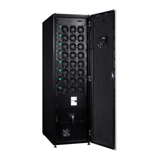
Page 17: Figure 2-1: Eaton 93Pr Ups
Figure 2-1: Eaton 93PR UPS Eaton 93PR 500 kW UPS User's and Installation Guide... -
Page 18: Figure 2-2: Position Indication
Input Switch Bypass Switch Output switch UPM Cabinet IO Cabinet Figure 2-2: Position Indication Eaton 93PR 500 kW UPS User's and Installation Guide... -
Page 19: Looking Inside The Ups System
2.1. Looking Inside the UPS System The system level static bypass in the 93PR 500kW UPS UPS cabinet determines the attainable output power of the UPS. The static bypass line consists of static switch and a backfeed protection isolation device connected in series. In addition, there is a system level control unit that constantly monitors the power delivered through the bypass line or to the input of the UPS. -
Page 20: Figure 2-3: 93Pr 500Kw Ups Wiring Diagram
Input Input Switch UPM 10 UPM 1 X N (1~10) Bypass Switch Backfeed Protection Battery Breaker (optional) Maintenance Output Bypass Switch Switch MBS Output Figure 2-3: 93PR 500kW UPS Wiring Diagram Eaton 93PR 500 kW UPS User's and Installation Guide... -
Page 21: Ups Operating Modes
Figure : Path of current through the UPS in Double Conversion Mode shows the path of electrical power through the UPS system when the UPS is operating in Double Conversion Mode. Eaton 93PR 500 kW UPS User's and Installation Guide... -
Page 22: Figure 2-4: Path Of Current Through The Ups In Double Conversion Mode
Bypass Mode and remains in that mode until the failure is corrected and the UPS is back in service. In an external parallel redundant system, each one UPS can be isolated from the system for service while the remaining UPSs support the load in double conversion. Eaton 93PR 500 kW UPS User's and Installation Guide... -
Page 23: Figure 2-5: Path Of Current Through The Ups In Energy Saver System
Energy Saver System increases system efficiency to 99 % when supplying 20-100 % nominal load, reducing energy losses by up to 80 %. Internal relay contacts Figure 2-5: Path of current through the UPS in Energy Saver System Eaton 93PR 500 kW UPS User's and Installation Guide... -
Page 24: Stored Energy And Battery Mode
If at any time during the battery discharge the input power becomes available again, K1 and K5 close and the UPS returns to normal operation. The UPS will also start to recharge batteries to restore the capacity. Eaton 93PR 500 kW UPS User's and Installation Guide... -
Page 25: Bypass Mode
2.3 UPS features The Eaton UPS has many features that provide cost-effective and consistently reliable power protection. The feature descriptions provide a brief overview of the UPS standard features. -
Page 26: Ups Features
Hot Sync technology is an algorithm that eliminates the single point of failure in a parallel system and therefore enhances the system reliability. The Hot Sync technology is incorporated in all 93PR UPSs, and it is utilised in both multi-module internal parallel and external parallel systems. -
Page 27: Top / Bottom Cable Entry Compatible
Top / Bottom cable entry compatible 93PR UPS can support both top cable entry and bottom cable entry, to achieve flexible system installation and deployment in the field. The customer power wires can pass through openings on the top rear or bottom rear of UPS cabinet, and then enter cabling route way and connect to UPS terminal blocks at rear of UPS. -
Page 28: Battery System
The 93PR 500kW UPS can be equipped with an external battery, and no internal batteries are available. For detailed battery specifications, see Chapter Technical data. -
Page 29: Chapter 3 Ups Installation Plan And Unpacking
NOTE Startup and operational checks must be performed by an authorized Eaton Customer Service Engineer, or the warranty terms specified in Warranty become void. This service is offered as part of the sales contract for the UPS. Contact service in advance (usually a two-week notice is required) to reserve a preferred startup date. -
Page 30: Table 3-1: Dimensions
When ignored, either one of these aspects can create an undesirable microclimate at the UPS location. If the environment created by this microclimate exceeds the Eaton UPS operating specification, the UPS reliability, over time, will be reduced. These same environmental extremes will also create reliability concerns for any servers that are exposed to them. -
Page 31: Figure 3-1: Ups Cabinet Clearances. See Table
• A = clearance at top of cabinet • B = clearance at back of cabinet • C = clearance at front of cabinet Figure 3-1: UPS Cabinet Clearances. See Table Eaton 93PR 500 kW UPS User's and Installation Guide... -
Page 32: Table 3-4: Air Conditioning Or Ventilation Requirements During Full Load Operation
The UPS ventilation requirements are shown in the following table: Table 3-4: Air conditioning or Ventilation Requirements During Full Load Operation Rating Heat Rejection (kVA) Heat Rejection (BTU/h x 1000) 500 kW 17915 71.1 Eaton 93PR 500 kW UPS User's and Installation Guide... -
Page 33: Figure 3-2: Ups Dimensions
Top View Left View Rear View Front View Right View Bottom View Figure 3-2: UPS Dimensions Eaton 93PR 500 kW UPS User's and Installation Guide... -
Page 34: Figure 3-3: Upm Dimensions
Rear View Left View Right View Top View Front View Figure 3-3: UPM Dimensions Eaton 93PR 500 kW UPS User's and Installation Guide... -
Page 35: Ups System Power Wiring Preparation
• A readily accessible disconnect device must be incorporated in all fixed input wiring. Eaton 93PR 500 kW UPS User's and Installation Guide... -
Page 36: Table 3-5: Rated And Maximum Currents For Rated Power And Voltage
Table 3-5: Rated and Maximum Currents for Rated Power and Voltage UPS Output/ UPS Output/ Rated Rectifier input Battery Rated UPM QTY Inverter Rated Bypass Rated voltage Rated current current current current 1085 10*50kW 1085 1085 9*50kW 8*50kW 7*50kW 6*50kW 5*50kW Eaton 93PR 500 kW UPS User's and Installation Guide... -
Page 37: Table 3-6: Maximum Support Multi-Core Cable Sizes
3*70mm 4*70mm 4*70mm 6*50kW 2*70mm 2*70mm 2*70mm 2*70mm 3*70mm 3*70mm 5*50kW 2*70mm 2*70mm 2*70mm 2*70mm 3*70mm 3*70mm NOTE Bypass fuse type should be greater than 10 times rated I t 20ms. Eaton 93PR 500 kW UPS User's and Installation Guide... -
Page 38: Table 3-8: Ups Power Cable Terminations
Inrush or Starting Current. Bypass and output overcurrent protection and bypass and output disconnect switches are to be provided by the user. For UPS wiring diagrams, see Chapter Looking inside the UPS system. Eaton 93PR 500 kW UPS User's and Installation Guide... -
Page 39: Ups System Interface Wiring Preparation
Alarm relay contacts have a maximum current rating of 5 A and a switched voltage rating of 30 Vac (RMS) and 30 Vdc. • Alarm relay wiring should be a minimum of 0.75 mm². Eaton 93PR 500 kW UPS User's and Installation Guide... -
Page 40: Inspecting And Unpacking The Ups Cabinets
User can remove the front and rear feet covers of the UPS cabinet, use the holes on the feet to install the UPS cabinet on the ground or channel steel (see the bottom view in Figure 3-2 for hole dimensions), and then reinstall the feet covers. Eaton 93PR 500 kW UPS User's and Installation Guide... -
Page 41: Figure 3-4: Straighten The Securing Tabs
While waiting for installation, protect the unpacked cabinet from moisture, dust, and other harmful contaminants. Failure to store and protect the UPS properly may void your warranty. securing tabs Figure 3-5: Remove wooden box Figure 3-4: straighten the securing tabs Figure 3-6: Remove cushioning Eaton 93PR 500 kW UPS User's and Installation Guide... -
Page 42: Figure 3-7: Remove The Shipping Bracket
Shipping Bracket Screws Shipping Bracket Shipping Bracket Screws Figure 3-7: Remove the shipping bracket Figure 3-8: Fork into Position Eaton 93PR 500 kW UPS User's and Installation Guide... -
Page 43: Instruction For Removing The Upm Module Packaging
Check whether the UPS is damaged during the process of transportation or not. Should any damage be observed or parts be found missing, do not start the machine. Contact the forwarder and distributor immediately. Figure 3-9: Instruction for Removing the UPM Module Packaging Eaton 93PR 500 kW UPS User's and Installation Guide... -
Page 44: Chapter 4 Ups System Installation
4.1. Steps to Install the UPS 93PR UPS can support top and bottom cable entry. The customer power wires and control wiring can pass through openings on the top rear of UPS cabinet connect to UPS terminal blocks at rear of UPS, see Figure : Gland Plate and Connector Locations. -
Page 45: Figure 4-1: Gland Plate And Connector Locations
Top Entry Top View Input Battery + Bypass Input Battery - Output Ground Rear View Entry Bottom Bottom View IO Cabinet UPM Cabinet Figure 4-1: Gland Plate and Connector Locations Eaton 93PR 500 kW UPS User's and Installation Guide... -
Page 46: Battery System Installation
EC directives are met and declare conformity. The default battery settings of the UPS are for 12 Vdc VRLA batteries. If requested to use other battery types, contact your Eaton representative. For the battery specification, see Chapter Battery specification. -
Page 47: Support Common Battery
For separate battery configuration, each 93PR frame connect to separate battery bank. And the battery settings between frames could be different but the backup time of whole UPS system is limited by the minimum battery bank. -
Page 48: Figure 4-3: Common Battery Configurations
The DC input voltage for 93PR is 400Vdc~580Vdc. 93PR support various DC source including VRLA, Lithium- ion, Ni-Cad, Supercaps and flywheel. For Lithium-ion battery application, battery BTR and detail information shall refer to the battery’s own BMS. Or you can contact Eaton for more integration application of BMS data on UPS’s HMI. -
Page 49: Installing A Remote Epo Switch
4.4. Installing Interface Connections 93PR UPS contains a total of five (5) signal input connectors for customers which can be used for giving remote control commands to the UPS. Customer interface connector CN5 can be used forthese purposes. Each input is a dry relay contact input and requires two wire signaling. -
Page 50: Installing Customer Input Signals Interface
External Battery Breaker Wiring Interface When using the original battery cabinet from the Eaton, the battery breaker interface wiring is provided with the cabinet. Connecting it requires only routing the wires from the cabinet to the bottom section of the UPS. -
Page 51: Installing Signal Interface Connections In Parallel System
This concerns also the EPO-signal. 4.5. Wiring Parallel 93PR UPS Systems The outputs of multiple 93PR UPS systems can be connected in parallel. Standard four units can be paralleled. The UPS static bypass power rating needs to be identical among all paralleled units. However, paralleled UPS cabinets can be housed with different number of UPM power modules. - Page 52 Ensure that each UPS static bypass is fed from a single common source, as is an external bypass switch if installed. If each UPS is fed with a separate rectifier source, please consult Eaton for advice on compatibility. Eaton 93PR 500 kW UPS...
-
Page 53: Figure 4-5: Principle Of Paralleled Ups Systems
Battery Battery UPS 3 UPS 3 Outputs from Outputs from UPSs UPSs Battery Battery UPS 4 UPS 4 Battery Battery Parallel UPS system connections Figure 4-5: Principle of Paralleled UPS Systems Eaton 93PR 500 kW UPS User's and Installation Guide... -
Page 54: Control Signals Overview
4.5.3. Installing Bypass Control Wiring During the installation, follow all the safety instructions given in the 93PR User’s and Installation Guide. 12-pin terminal block for external parallel control signals is accessible on the right side of the communication interface, on the top section of the UPS. (See Figure : Communication interfaces.) -
Page 55: Figure 4-7: Simplified Can And Pull-Chain Wiring For Parallel Upp System
This drawing is for distributed bypass wiring purposes and is not a floor layout plan. UPPs can be placed in any physical order. NOTE External CAN connections between UPPs require 3-core shielded twisted pair wire (22AWG). Figure 4-8: CAN and Pull-Chain Wiring for Parallel UPS Eaton 93PR 500 kW UPS User's and Installation Guide... -
Page 56: Chapter 5 Communication Interfaces
Chapter 5 COMMUNICATION INTERFACES This section describes the communication features of the 93PR UPS. The UPS has the following communication interfaces: Mini-slot 1 Mini-slot 2 Mini-slot 3 USB device (connection to computer) Emergency Power Off (EPO) Relay output USB host (connection to accessories) -
Page 57: Mini-Slots
5.1. Mini-slots The 93PR UPS has three Mini-slot communication bays. The UPS is compatible with the following Mini-slot cards: • Gigabit Network Card The Eaton Gigabit Network Card (Network-M2) is Eaton’s latest UPS network management card that delivers IT professionals with new and exciting capabilities and features. With better speed and cybersecurity, the Gigabit Network Card improves business continuity by providing warnings of pending issues to administrators and helping to perform orderly shutdown of servers and storage. -
Page 58: Figure 5-4: Industrial Gateway Card
• Industrial Gateway Card The Eaton Industrial Gateway Card (INDGW-M2) combines the features of an SNMP agent, HTTP/web server and a Modbus card to facilitate remote monitoring of your UPS system through any Building Management System. Enjoy the freedom to customize and schedule actions, like shutdown protocols and load shedding, and receive immediate notifications during power events, without having to be onsite. -
Page 59: Intelligent Power Software
• Industrial relay card The Mini-Slot Industrial Relay Card provides a way of connecting the 93PR to industrial and electrical monitoring systems. It also enables a wide range of control applications by allowing up to 250 volts and 5 Amperes through its 5 relay connections. -
Page 60: Signal Input Monitoring
UPS. This feature is useful if the UPS is located in a remote area where the UPS horn may not be heard immediately. NOTE Contacts should not be operated in excess of 30 Vac (RMS) and 30 Vdc at 5 A maximum. Eaton 93PR 500 kW UPS User's and Installation Guide... -
Page 61: Chapter 6 Ups Operating Instructions
Before operating the UPS, confirm the UPS nominal voltage and frequency from display by selecting Settings -> Info. If the UPS need to be operated with another voltage or frequency, contact your closest Eaton office or Eaton authorized partner. •... -
Page 62: Lps
Red lighting Red lighting 6.2. Control Panel The following sections describe the UPS control panel and how to monitor and control UPS operation. Figure 6-2: UPS Color Touch screen Control Panel (Typical) Eaton 93PR 500 kW UPS User's and Installation Guide... -
Page 63: Status Indicators
If the level 1 password is enabled, you need to sign in. Press the lock button in the upper right corner of the screen. Type your passcode and press OK. You are signed in. Press Continue to return to the previous screen. Eaton 93PR 500 kW UPS User's and Installation Guide... -
Page 64: Figure 6-3: Parts Of The Touch Screen
Figure 6-4: Sign In or Password Request Screen The UPS st atus area automatically displays the Eaton model number, current time and date, ac- tive alarms, active notices, and load percent and batter y run time for the UPS. If the Environmental Monitoring Probe is installed, the temperature and humidity sensed by the probe will also be displayed. -
Page 65: Using The Main Menu Buttons
Module controls Start charger, Run battery test /Shut down module / Start mod-ule Configurable user settings. See Chapter 11 APPENDIX A: User Settings Setting group settings on page 84 for de-tails. Eaton 93PR 500 kW UPS User's and Installation Guide... -
Page 66: System Events
20 seconds for the UPS system to achieve Double Conversion Mode. 10. The UPS system is now operating in Double Conversion Mode and the NORMAL status indicator is illuminated in all UPSs in the system. Eaton 93PR 500 kW UPS User's and Installation Guide... -
Page 67: Starting The Ups System In Bypass Mode
The UPS system is now operating in Bypass Mode and the BYPASS status indicator is illuminated. The UPM status indicates READY. The system status indicates ON BYPASS. DANGER Power is present inside the UPS cabinets. Eaton 93PR 500 kW UPS User's and Installation Guide... -
Page 68: Transfer From Bypass To Double Conversion Mode
DANGER Power is present inside the UPS cabinet until the upstream input feeder circuit breaker is opened. Eaton 93PR 500 kW UPS User's and Installation Guide... -
Page 69: Energizing The Critical Load
Power is present inside the UPS cabinet until the upstream input feeder circuit breaker is opened. 6.3.1 To restart the UPS system, follow the procedure in Chapter Starting the UPS system in Double 6.3.2 Conversion Mode or Chapter Starting the UPS system in Bypass Mode. Eaton 93PR 500 kW UPS User's and Installation Guide... -
Page 70: Ups Control Instructions
Press the Controls button in the main menu. The System controls screen is displayed. On the System controls screen, press UPS controls. On the UPS control screen, select Shut down UPS. Eaton 93PR 500 kW UPS User's and Installation Guide... -
Page 71: Enabling And Disabling The Battery Charger
Options supplied by the N+X parallel redundancy system The 93PR can be installed from 1 up to 10 UPS modules in its cabinet and the user can choose the N+X parallel redundancy solution easily. Suppose the load is 80kVA and the optional solution is listed in the... - Page 72 The 93PR UPS module is hot swappable, but to perform this process, some definite procedures must be complied with. When performing the UPS modules adding, reducing and changing online, the operating instructions must be strictly followed. Online Adding the UPS Module Select a slot in the UPS that has not been installed with UPM for installation, only one UPM can be in- stalled at a time, after the UPM installation is completed, the next UPM can be installed;...
-
Page 73: Figure 6-7: Upm Module Location
To replace UPM, please implement removing UPM steps and then do adding UPM steps. WARNING Ensure the lock has to unlock the state, when pull out the UPM. Position Lock Figure 6-7: UPM Module Location Eaton 93PR 500 kW UPS User's and Installation Guide... -
Page 74: Starting The Upms
On the System controls screen, press Module controls. Select module screen is displayed. Select the UPM you want to shut down (UPM 1 - UPM 10). On the UPM control screen, select Shut down module. Eaton 93PR 500 kW UPS User's and Installation Guide... -
Page 75: Using The Remote Emergency Power-Off Switch
NOTE The following instructions are for the Eaton Corporation-supplied EPO switch. If a customersuppliedEPO switch is used, it may not activate in the same manner; refer to the operating instructions provided with the switch. -
Page 76: Transfer The Ups From Double Conversion Mode To Maintenance Bypass Mode
Input switch (closed) Vertical position switch (closed) Bypass Vertical position MBS switch (open) Horizontal position switch (closed) Output Vertical position UPM cabinet IO cabinet Front view Figure 6-8: Double Conversion Mode Eaton 93PR 500 kW UPS User's and Installation Guide... -
Page 77: Figure 6-9: Maintenance Bypass Mode
Input switch (open) Horizontal position Bypass switch (open) Horizontal position MBS switch (closed) Vertical position Output switch (open) Horizontal position IO cabinet UPM cabinet Front view Figure 6-9: Maintenance Bypass Mode Eaton 93PR 500 kW UPS User's and Installation Guide... -
Page 78: Transfer Ups From Maintenance Bypass To Double Conversion Mode
Perform the UPS start-up procedure (bypass mode) in Chapter 6.4.2 Starting the UPS system in Bypass mode. Turn OFF the MBS, and cut off the UPS maintenance bypass (MBS) output. Refer the chapter 6.4.4 to transfer the Maintenance Bypass Mode to Double Conversion Mode.. Eaton 93PR 500 kW UPS User's and Installation Guide... -
Page 79: Figure 6-11: Double Conversion Mode
Input switch (closed) Vertical position switch (closed) Bypass Vertical position MBS switch (open) Horizontal position switch (closed) Output Vertical position UPM cabinet IO cabinet Front view Figure 6-11: Double Conversion Mode Eaton 93PR 500 kW UPS User's and Installation Guide... -
Page 80: Chapter 7 Ups Maintenance
• When replacing batteries, use the same number of sealed, lead-acid batteries. • Proper disposal of batteries is required. Refer to your local codes for disposal requirements. Eaton 93PR 500 kW UPS User's and Installation Guide... -
Page 81: Performing Preventive Maintenance
The UPS system requires very little preventive maintenance. However, the system should be inspected periodically to verify that the units are operating normally and that the batteries are in good condition. Majority of the work must be performed by Eaton authorized service personnel. Only the actions described in Chapter 7 .2.1 7 .2.2... -
Page 82: Annual M Aintenance
Follow ALL applicable, local regultions for storage, handling and disposal of batteries and battery materials. Figure 7-2: Recycling Batteries Symbol 7.4. Maintenance Training For more information about training and other services, contact your Eaton representative. Eaton 93PR 500 kW UPS User's and Installation Guide... -
Page 83: Chapter 8 Technical Data
Chapter 8 TECHNICAL DATA For complete technical specification, contact your Eaton representative. Due to continuous product improvement programs, specifications are subject to change without notice. 8.1. Standards Table 8-1: Standards IEC 62040-1, IEC 60950-1 Safety EMC, Emissions IEC 62040-2 2005... -
Page 84: Ups System Input
Input Current Distortion at Rated Input Current, iTHD < 3 % Rectifier Ramp-up, Rectifier Start and Load Step 5 A/s per UPM (default), configurable. Min 1A/s per UPM Backfeed Protection Yes, for rectifier and bypass lines Eaton 93PR 500 kW UPS User's and Installation Guide... -
Page 85: Ups System Output
See Table : Rated and maximum currents for rated Output Current power and voltage on page 31 Load Power Factor, (Rated) From 0.8 lagging to 0.8 leading Load Power Factor, (Permitted Range) Eaton 93PR 500 kW UPS User's and Installation Guide... -
Page 86: Battery Specification
Single UPM default 25A, configurable, max 40A per UPM Battery Start Option Note! For external battery connection, 48 Vdc Shunt release signal wiring from the UPS must be connected to the aux- iliary signal connection of the battery breaker. Eaton 93PR 500 kW UPS User's and Installation Guide... -
Page 87: Ups Environmental Specifications
Storage condition for UPS and spare parts store one year (refer unit SN). Place Indoor Dusty Well Storage Temperature <40°C Storage Humidity < 70% RH Other With original package Please re –evaluate the storage time if can not meet above storage condition. Eaton 93PR 500 kW UPS User's and Installation Guide... -
Page 88: Chapter 9 Warranty
If the product fails to meet its published specifications due to a defect in material and workmanship, covered by this warranty, the seller will repair or replace the warranted product. Such repair or replacement will be made by Eaton or by a service provider approved by Eaton. -
Page 89: Chapter 10 Installation Checklist
(OPTIONAL) Accessories are mounted in installed locations and wiring is terminated inside the UPS cabinet. (OPTIONAL) Startup and operational checks are performed by an authorized Eaton Customer Service Engineer. Eaton 93PR 500 kW UPS User's and Installation Guide... -
Page 90: Chapter 11 Appendix A: User Settings
Change the level 1 password, or remove the password on Control P/W level 1 level 1. The default value is 1111. Config P/W level 2 Change the level 2 password. The default value is 101. Eaton 93PR 500 kW UPS User's and Installation Guide... - Page 92 614-40061-00...
Need help?
Do you have a question about the 93PR and is the answer not in the manual?
Questions and answers