Table of Contents
Advertisement
Quick Links
Carrington Trim Series
Carrington Trim Series with TA-10 Flow Control Spindle &
T-12A Cap Assembly
Installation & Operation Instructions
Model Numbers
TRIM ONLY
4400-TRM
Shower Valve Trim
4401-TRM
Shower Trim
4403-TRM
Hand Shower Trim
4405-TRM
Shower/Hand Shower Trim
4406-TRM
Tub/Shower/Hand Shower Trim
Compliance
•
ASME A112.18.1/CSA B125.1
Warranty
Limited Lifetime - to the original end purchaser in consumer/residential installations.
5 Years - for industrial/commercial installations.
Refer to www.symmons.com/warranty for complete warranty information.
Go to www.symmons.com/register to register your Symmons product.
Carrington
TRIM, TA-10, T-12A
4400TRMTC
Shower Valve Trim
4401TRMTC
Shower Trim
4403TRMTC
Hand Shower Trim
4405TRMTC
Shower/Hand Shower Trim
4406TRMTC
Tub/Shower/Hand Shower Trim
T-12A
TA-10
®
4400-TRM
4400TRMTC
4403-TRM
4405-TRM
4403TRMTC
4405TRMTC
4401-TRM
4401TRMTC
4406-TRM
4406TRMTC
Advertisement
Table of Contents

Related Manuals for Symmons Carrington Trim Series


Summary of Contents for Symmons Carrington Trim Series
- Page 1 Carrington ® Carrington Trim Series Carrington Trim Series with TA-10 Flow Control Spindle & T-12A Cap Assembly Installation & Operation Instructions Model Numbers TRIM ONLY TRIM, TA-10, T-12A 4400-TRM 4400TRMTC Shower Valve Trim Shower Valve Trim 4401-TRM 4401TRMTC Shower Trim...
- Page 2 1. Recommended Tools FIGURE 1 Adjustable Wrench Allen Wrench (3mm) Drill Phillips Screwdriver Safety Glasses Thread Seal Tape 2. Dimensions Measurements FIGURE 2 Ø 2-5/8", 67 mm 9-1/4", 235 mm 1/2" NPT 2-1/8", 54 mm 1/2", 13 mm Male 1/2" IPS thread must be recessed 1/4"...
- Page 3 3. Parts Breakdown (Model Numbers Ending in TRMTC) Replacement Parts LIMIT STOP Item Description Part Number SCREW Cap Assy. T-12A Flow Control Spindle TA-10 IMPORTANT: Model numbers ending in TRMTC coordinate with Temptrol pressure balancing valves ordered with Test Cap. The Test Cap is used to allow pressurization of system.
- Page 4 7. Parts Breakdown Replacement Parts FIGURE 7 Item Description Part Number Showerhead 442SH Shower Arm Set Screw Handle DF-28-LPO Flange O-ring Lock Nut T-20-PL Washer 40B-PL Dome Cover DF-11 Mounting Screws DF-14 Diverter Escutcheon Shower Plate 7.5-ETCH Hand Shower 442W Wall Cradle Screws EF-106...
- Page 5 Secure with screw (FIGURE 8.3). FIGURE 8.3 9. Installation - Diverter Valve Trim 1) Secure escutcheon to Symmons diverter valve using FIGURE 9.1 FIGURE 9.2 mounting screws (FIGURE 9.1). 2) Install dome cover and washer to valve. Secure with lock nut by by turning clockwise (FIGURE 9.2).
- Page 6 11. Installation - Slide Bar Assembly 1) Place mounting plate in position. Mark and drill 3/16" FIGURE 11.1 FIGURE 11.2 holes for tile anchors, 5/16" holes for drywall anchors. Install anchors (FIGURE 11.1). Note: For dry wall 1/2" thick or less, insert anchor tool into drywall anchor to secure behind wall prior to installing wall cradle.
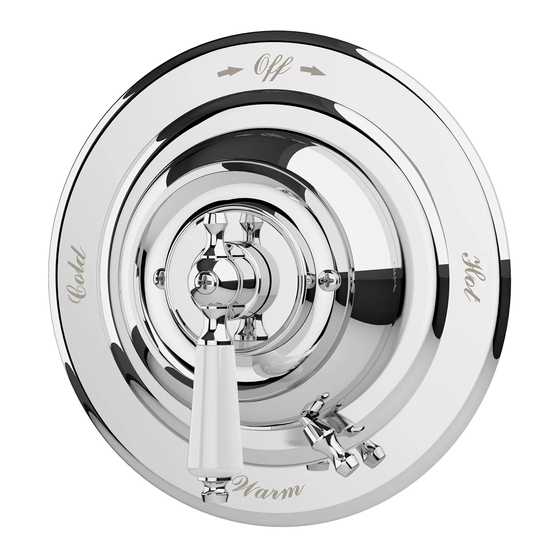
- Page 7 12. Operation (Temperature Control) 1) Turn shower handle counter-clockwise FIGURE 12.1 FIGURE 12.2 FIGURE 12.3 approximately 1/4 turn to put valve in cold position (FIGURE 12.1). 2) Turn shower handle counter- clockwise approximately 1/2 turn to put valve in warm position (FIGURE 12.2). 3) Turn shower handle counter- clockwise approximately 3/4 turn to put valve in hot position (FIGURE 12.3).
- Page 8 For more information, go to www.P65Warnings.ca.gov. ■ ■ ■ ■ Symmons Industries, Inc. 31 Brooks Drive Braintree, MA 02184 Phone: (800) 796-6667 Fax: (800) 961-9621 ■ ■ ■ ■ Copyright © 2019 Symmons Industries, Inc. symmons.com gethelp@symmons.com ZV-3278 REV A 062419...
Need help?
Do you have a question about the Carrington Trim Series and is the answer not in the manual?
Questions and answers