Advertisement
Quick Links
Shower System
Installation Brief
Model Number
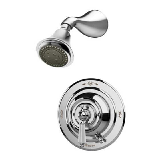
S-4401 Shower System
Decorative Finish Code
append to part numbers if applicable
-STN Satin Nickel
-- Chrome (standard)
Rough-in Installation
Control valve, piping & fittings
Reference rough-in dimension illustration
on page 2 as required.
1)
Determine wall thickness
■ Determine type of wall and wall
thickness where valve will be mounted.
■ Consider whether to use mounting plate
by reviewing figure 2 below.
■ Skip ahead to
if mounting
Step 3
plate will not be used.
2)
Attach mounting plate to valve
Seat mounting plate against valve
assembly as illustrated in figure 1.
Walls for using T-177 mounting plate
Fiberglass or acrylic walls (required)
Plaster or other type walls (optional)
1/16" (2 mm) min 1/2" (13 mm) max
Protective shield
When mounting plate is used,
then shield is optional for
protecting end of valve during
installation.
"snap on-off"
p/n T-176
wall cutout hole size
3-1/2" ( 95 mm) min
Carrington
S-4401
Tools & Materials
Plumbers
3)
Attach protective shield
■ Reference figure 2 to determine
whether shield is required.
■ Attach plastic protective shield by
snap fitting over end of valve spindle.
nished
wall
p/n T-177
4" (101 mm) max
Figure 2 Mounting valve
Putty
1
2
3
4
Figure 1 Mounting plate
Dry wall, plaster or other type wall
1/2" (13 mm) or greater
(51 mm ± 13 mm)
Ensure valve's
mounting plate
is ush against
inner wall
Finished wall must be
ush with back side of
protective shield surface
Protective shield
"snap on-off"
(required when
mounting plate
is not used)
wall cutout hole size
3-1/2" ( 89 mm) min
4" (101 mm) max
™
Need Help?
Contact Symmons customer service
at (800) 796-6667, (781) 848-2250,
customerservice@symmons.com
Mon - Fri 7:30 am - 7:00 pm EST
Please check Symmons website
for technical help, the latest product
information and warranty policy.
www.symmons.com/service
4)
Install piping, fittings and
control valve
Piping and fittings not supplied
■ Control Valve
Install valve through cutout hole in
wall as specified in figure 2 below and
dimension illustration on page 2.
■ Showerhead (S on valve)
Pipe from outlet port on valve marked
to showerhead mounting arm location.
■ Hot & Cold Supply (H & C)
Pipe hot water supply to valve input
marked
and cold water supply to
H
valve input marked
nished wall
2" ± 1/2"
pipe centerline
to nished wall
S
.
C
Advertisement

Related Manuals for Symmons Carrington Shower System


Summary of Contents for Symmons Carrington Shower System
- Page 1 Need Help? Model Number Tools & Materials S-4401 Shower System Contact Symmons customer service at (800) 796-6667, (781) 848-2250, customerservice@symmons.com Decorative Finish Code Mon - Fri 7:30 am - 7:00 pm EST append to part numbers if applicable ...
- Page 2 ■ Check for leaks around valve do not allow the valve to flow at least 1.5 gpm. assembly and all pipe fittings. Dimensions Carrington Shower System, S-4401 1/2" (13 mm) 1/2"-14 NPT 3-1/8" (79 mm)
- Page 3 Parts Assembly Temptrol Shower Control Valve, S-4001-BODY hot seat Seat repair kit Hot seat cold seat (TA-4) removal tool (T-35A) Shower supply Cold seat Temptrol removal tool “C” cold supply (T-35B) Control Valve seat Cold “H” seat hot supply Tub supply plug 5/16"...
- Page 4 ■ ■ Symmons Industries, Inc. 31 Brooks Drive Braintree, MA 02184 ■ (800) 796-6667, (781) 848-2250 Fax (800) 961-9621, (781) 664-1300 ■ Website: www.symmons.com Email: customerservice@symmons.com ■ ■ © 2010 Symmons Industries, Inc. Printed in U.S.A. ZV-991 121510...
Need help?
Do you have a question about the Carrington Shower System and is the answer not in the manual?
Questions and answers