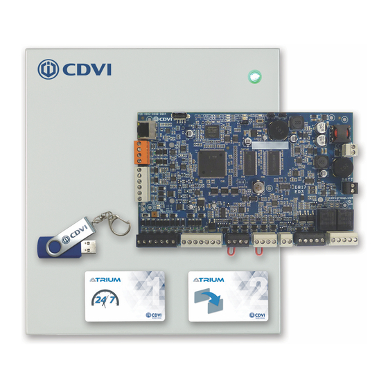
CDVI ATRIUM A22K Quick Start Manual
2-door / 4-reader controller
Hide thumbs
Also See for ATRIUM A22K:
- Manual (60 pages) ,
- Quick start manual (4 pages) ,
- Manual (44 pages)
Advertisement
Quick Links
PLAN YOUR A22K NETWORK CONNECTIVITY
1
500 door system (100 doors connected IP + 400 doors connected RS485)
the "Master" controller to manage the others. These forty-nine (49) others are defined as "Sub-Controllers".
"MASTER"
CONTROLLER
The "Master" controller
manages up to forty nine (49)
"Sub-Controllers".
(100 doors fully IP)
AES256
E N C R Y P T I O N
IP Network
Maximum 300 ft (100 m)
+12V DC
A+
B-
Input 1
Input 2
Output 1
+12V DC
Output 2
BUZ GRN RED D1
D0 GND 12V
BUZ GRN RED D1
D0 GND
12V
C1
GND
REX1
12V
C2
GND
REX2
12V
A22K "Master" or "Sub-Controllers"
RS485 port (orange connector).
Maximum 4000 ft
(1220 m)
+12V DC
+12V DC
A+
A+
B-
Input 1
Input 2
B-
Output 1
+12V DC
Output 2
ENCLOSURE
Input 1
TAMPER
INPUT
INPUT
SWITCH
READER DOOR 1
READER DOOR 2
DOOR 1
DOOR 2
INPUT
BUZ GRN RED D1
D0 GND 12V
BUZ GRN RED D1
D0 GND
12V
C1
GND
REX1
12V
C2
GND
REX2
12V
GND
TMP
LK1+ LK1-
A22K set as "Expander"
Input 2
Output 1
+12V DC
READER DOOR 1
Output 2
IP CONNECTIVITY
Out of the box the A22K is ready for IP connectivity, fifty (50) A22K per account.
If you have more than one A22K controller per account, one must be set as
+12V DC
A+
B-
Input 1
Input 2
Output 1
+12V DC
Output 2
BUZ GRN RED D1
D0 GND 12V
BUZ GRN RED D1
D0 GND
LAN or WAN
+12V DC
+24V DC
-
A+
B-
Input 1
Input 2
+12V DC
Output 1
-
+12V DC
Output 2
GND
TMP
LK1+ LK1-
C1 NO1 NC1
LK2+ LK2-
C2 NO2 NC2
BUZ GRN RED D1
"SUB-CONTROLLERS"
Up to forty-nine (49) A22K defined as "Sub-Controllers".
RS485 CONNECTIVITY
An A22K can be set as an "Expander". Up to four (4) can be connected to the
RS485 network (orange connector) of the "Master" and each "Sub-Controller".
ETHERNET
PORT
+12V DC
Use twisted pair wiring
RS485
for RS485 connection
LOCAL
(1 pair for ground and 1
A+
pair for A+ B-)
BUS
B-
Input 1
EXTRA
Input 2
INPUTS/
Output 1
OUTPUTS
+12V DC
+12V DC
+24V DC
-
A+
Output 2
B-
Input 1
Input 2
+12V DC
Output 1
-
+12V DC
Output 2
ENCLOSURE
TAMPER
LOCK
LOCK
INPUT
INPUT
SWITCH
DOOR 1
DOOR 2
READER DOOR 1
READER DOOR 2
DOOR 1
DOOR 2
INPUT
C1 NO1 NC1
LK2+ LK2-
C2 NO2 NC2
BUZ GRN RED D1
D0 GND 12V
BUZ GRN RED D1
D0 GND
12V
C1
GND
REX1
12V
C2
GND
REX2
12V
GND
TMP
A22K set as "Expander"
READER DOOR 2
A22K
QUICK START GUIDE
+24V DC
-
+12V DC
-
12V
C1
GND
REX1
12V
C2
GND
REX2
12V
GND
TMP
LK1+ LK1-
C1 NO1 NC1
LK2+ LK2-
C2 NO2 NC2
+24V DC
-
+12V DC
-
D0 GND 12V
BUZ GRN RED D1
D0 GND
12V
C1
GND
REX1
12V
C2
GND
REX2
12V
GND
TMP
LK1+ LK1-
C1 NO1 NC1
LK2+ LK2-
C2 NO2 NC2
ETHERNET
LOCAL BUS
24V DC INPUT/
BATTERY/
How to set an A22K as an "Expander"
MODULE TYPE
SYSTEM STATUS
On power OFF, move the "Module Type"
jumper setting to the two pins closest to "EX".
EX
+12V DC
+24V DC
-
A+
B-
Input 1
Input 2
+12V DC
Output 1
-
+12V DC
Output 2
ENCLOSURE
TAMPER
LOCK
LOCK
INPUT
INPUT
SWITCH
DOOR 1
DOOR 2
READER DOOR 1
READER DOOR 2
DOOR 1
DOOR 2
INPUT
LK1+ LK1-
C1 NO1 NC1
LK2+ LK2-
C2 NO2 NC2
BUZ GRN RED D1
D0 GND 12V
BUZ GRN RED D1
D0 GND
12V
C1
GND
REX1
12V
C2
GND
REX2
12V
GND
A22K set as "Expander"
INPUT
DOOR 1
2-DOOR / 4-READER CONTROLLER
Communication between the
"Master" controller and
"Sub-Controllers" is
established via TCP/IP ONLY.
+12V DC
+24V DC
-
A+
B-
Input 1
Input 2
Output 1
+12V DC
+12V DC
-
Output 2
BUZ GRN RED D1
D0 GND 12V
BUZ GRN RED D1
D0 GND
12V
C1
GND
REX1
12V
C2
GND
REX2
12V
GND
TMP
LK1+ LK1-
C1 NO1 NC1
LK2+ LK2-
C2 NO2 NC2
STATUS
LOCK 1 & 2
JUMPER SETTING
CT
DO NOT
use IP connection
when an A22K is set as an
"Expander".
+24V DC
+24V DC
+12V DC
-
A+
B-
Input 1
Input 2
+12V DC
Output 1
-
+12V DC
Output 2
ENCLOSURE
LOCK
LOCK
INPUT
INPUT
DOOR 1
DOOR 2
READER DOOR 1
READER DOOR 2
DOOR 1
DOOR 2
TMP
LK1+ LK1-
C1 NO1 NC1
LK2+ LK2-
C2 NO2 NC2
BUZ GRN RED D1
D0 GND 12V
BUZ GRN RED D1
D0 GND
12V
C1
GND
REX1
12V
C2
GND
REX2
12V
ENCLOSURE
A22K set as "Expander"
TAMPER
+12V DC
INPUT
LOCK
SWITCH
DOOR 2
DOOR 1
INPUT
INPUT
+24V DC
POWER
-
SUPPLY
BATTERY
+12V DC
BACKUP
-
-
+24V DC
-
+12V DC
-
TAMPER
LOCK
LOCK
SWITCH
INPUT
DOOR 1
DOOR 2
GND
TMP
LK1+ LK1-
C1 NO1 NC1
LK2+ LK2-
C2 NO2 NC2
LOCK
-
DOOR 2
Advertisement

Related Manuals for CDVI ATRIUM A22K


Summary of Contents for CDVI ATRIUM A22K
- Page 1 A22K 2-DOOR / 4-READER CONTROLLER QUICK START GUIDE PLAN YOUR A22K NETWORK CONNECTIVITY 500 door system (100 doors connected IP + 400 doors connected RS485) IP CONNECTIVITY Out of the box the A22K is ready for IP connectivity, fifty (50) A22K per account. If you have more than one A22K controller per account, one must be set as the “Master”...
- Page 2 A22K 2-DOOR / 4-READER CONTROLLER Input 1 QUICK START GUIDE EXTRA Input 2 INPUTS/ Output 1 OUTPUTS +12V DC FIX METAL ENCLOSURE & A22K PCB Output 2 holder Install indoors in a safe and secure location. ETHERNET ETHERNET LOCAL BUS STATUS LOCK 1 &...
- Page 3 A22K 2-DOOR / 4-READER CONTROLLER QUICK START GUIDE BATTERY +12V DC BACKUP CONNECT THE LOCK How to set the “Lock Output” for By default, the lock output is set for door strike (“Fail Secure”). The output Electromagnetic Lock (Maglock)? is at 0 VDC to keep the door locked and toggles to 12 VDC during 5 sec., on ENCLOSURE access granted or request-to-exit, to unlock the door.
- Page 4 / delete a user, create and assign access levels to a user, etc. Simply install the “ATRIUM Finder” application (Apple Store or Google Play) and visit the CDVI website for all video tutorials on basic configuration via the embedded web server: https://www.cdvi.ca/cdvi-academy/videos/ Use the FREE ATRIUM software for advanced configuration (PC only).
Need help?
Do you have a question about the ATRIUM A22K and is the answer not in the manual?
Questions and answers