
Subscribe to Our Youtube Channel
Related Manuals for CDVI ATRIUM KRYPTO A22K1BT


Summary of Contents for CDVI ATRIUM KRYPTO A22K1BT
- Page 1 A22K High Security Access Control 2-Door/4-Reader Module FULLY ENCRYPTED w w w. c dv i. ca...
-
Page 2: Table Of Contents
7] WARRANTY - TERMS & CONDITIONS . . . . . . . . . . . . . . . . . . . . . . . . . . . . . . . . . . . . . . . . . . . . .39 Copyright (C) 2019 CDVI. All rights reserved. ATRIUM Access Control is protected by copyright law and international treaties. -
Page 3: Product Presentation
• 1000 access levels • 256 floor levels • 250 schedules each supporting 100 time periods • Full calendar with leap year support • Firmware upgradable • FREE management software • Maintenance-friendly snap on terminal connectors • Comprehensive LED status indicators cdvi.ca... -
Page 4: What's New
ENCRYPTION New Microprocessor CDVI Encryption • HTTPS enabled • IPV6 ready • RS-485 encrypted reader BUS using CDVI KRYPTO reader • Supports 2 readers per port (Entry/Exit) • OSDP-2 compatible AES 128 Encryption (using Mifare DESFire EV2 card) KRYPTO High Security Card Reader •... - Page 5 Say “NO” to card cloning with ATRIUM’s unique KRYPTO high security solution. Eliminate complex and arduous programming using the ATRIUM A22K controller, CDVI Mifare DesFire EV2 credentials and K1 readers. System-wide AES encryption stops card cloning and provides end-to-end security. Whether you remote in from the internet or connect on your network you can be sure KRYPTO has you covered.
-
Page 6: Notes And Recommendations
Note: All circuits are power limited. UL 294 COMPLIANCE NOTICE CDVI declared the following levels: Destructive Attack Level I, Line Security Level IV, Endurance Level IV, Standby Power Level IV. Operation of the product shall not prevent the functionality of the emergency exit functions. -
Page 7: Recommended Wiring
4 x Auto-recognition High Security RS485 ports (if set as entry/exit door) Keypads 2 x Wiegand Keypad with Multiple Protocol Support (Wiegand 8-bit & 26-bit) 6 zone inputs (up to 12 using ZONE DOUBLING) supporting individual WIRE CUT & Multi-Purpose Inputs WIRE SHORT supervision. Box Tamper Normally Closed (N.C.) contact cdvi.ca... - Page 8 One 12Vdc 7Ah rechargeable acid/lead or gel cell backup battery (UL/ULC: YUASA #NP7-12 Battery Capacity recommended, Europe: CDVI B7AH recommended). Ensure proper polarity. 250mA (default), 500mA, or 1A. Refer to the ATRIUM system manual to modify the battery Charging Current charging current.
-
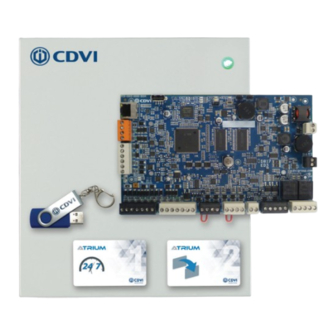
Page 9: Package Contents
Varistor for AC wires, for for DC door Fastener 1K Resistor 2 .2K Resistor door strikes or Installation backup battery strikes or (PCB Holder) maglocks (400mm) maglocks 1 pair 1 pair If any item is missing, please notify your distributor immediately. cdvi.ca... -
Page 10: Location And Mounting
2.4m (8ft.) from high voltage equipment or wiring and from electrical equipment likely to generate interference 1.2m (4ft.) from telephone equipment or lines and 8m (25ft.) from transmitting equipment The system’s location and wiring methods shall be in accordance with the National Electrical Code, ANSI/NFPA 70. cdvi.ca... -
Page 11: Mounting Instructions
Installing tamper switches allows the A22K to detect when the cabinet door is opened and/or when the cabinet is removed from the wall. If needed install the tamper switch(es) as follows: Metal box holes where to fix the wall tamper switch cdvi.ca... - Page 12 Install the wall tamper switch using the supplied bolts and nuts as shown in the following picture. Install the tamper switch plastic spacer on the back at bottom left side of Cabinet Side View the box as show in the following picture. Spacer Cabinet Door Spacer Screw Spacer cdvi.ca...
- Page 13 Refer to page 16 for wiring diagram. Fix the tamper switch to the bracket then mount the bracket on the mounting flange Bracket Door Tamper Switch Door Tamper Switch Mounting Flange cdvi.ca...
-
Page 14: Installing The Box Lock
However this should be done only once the installation is completed. Use the 4 screws supplied to secure the box cover to its base as shown in the following picture. cdvi.ca... -
Page 15: Fixing The Box To Its Location
Install the box to its location using 4 screws (not supplied) as shown in the following picture. If the wall tamper switch is used, make sure that the tamper switch arm moves freely and is completely pushed in when the enclosure is installed on the wall. cdvi.ca... -
Page 16: Installing The A22K Pc Board
Install the 5 fasteners (PCB holder) supplied respectively to the box holes identified in red in the following picture. Install the A22K PCB by aligning the fasteners with the corresponding PCB holes and pressing firmly to secure the PCB in place. cdvi.ca... -
Page 17: Wiring Diagram
“Sub-Controllers”. ATRIUM can support a total of 500 doors (100 doors connected IP + 400 doors connected RS485). Simply adjust the “Module Type” jumper setting as shown below. Module Type Jumper Setting (Controller or Expander) Module is set as a Module is set as a “2-Door Controller” “2-Door Expander” (Default Setting) cdvi.ca... -
Page 18: A22K Network Connectivity Wiring Diagram
SWITCH +12V DC READER DOOR 1 READER DOOR 2 DOOR 1 DOOR 2 DOOR 1 INPUT Output 2 cdvi.ca BUZ GRN RED D1 D0 GND 12V BUZ GRN RED D1 D0 GND REX1 REX2 LK1+ LK1- C1 NO1 NC1 LK2+ LK2-... - Page 19 READER DOOR 1 READER DOOR 2 DOOR 1 DOOR 2 DOOR 1 DOOR 2 INPUT BUZ GRN RED D1 D0 GND 12V BUZ GRN RED D1 D0 GND REX1 REX2 LK1+ LK1- C1 NO1 NC1 LK2+ LK2- C2 NO2 NC2 cdvi.ca...
-
Page 20: Box Tamper Switches
Connect one terminal of the tamper switch to the “TMP” terminals using the supplied wire. Connect the other terminal of the same tamper switch to the “GND” terminals using the supplied wire. If you do not use the tamper switch, connect a wire between the “TMP” and “GND” terminals. cdvi.ca... -
Page 21: Readers And Keypads
LK2+ LK2- C2 NO2 NC2 OPTION OF ENTRY/EXIT READERS Blue wire not used ON THE SAME PORT IMPORTANT: That option can ONLY be done with CDVI RS485 high security card readers. ENTRY EXIT Blue wire Blue wire to not used A22K GND terminal cdvi.ca... - Page 22 The optional entry/exit readers on the same port are not compatible with Wiegand readers. Please note that the A22K provides 12Vdc output. Connecting a device (keypad or reader) requiring a different voltage may damage the reader or keypad and void the A22K warranty. cdvi.ca...
-
Page 23: Inputs
Remove the jumper before installing the door contact N.C. +12Vdc N.C. REX1 N.C. Door Contact Com. Door 1 Factory Default Input Settings (same settings for door 2) See “Recommended Wiring” section for more information on wiring type, size, and maximum length. cdvi.ca... - Page 24 WIRE CUT supervision: No (Factory Default) Single with wire cut Single with wire cut and supervision short circuit (EOL) supervision Input 1 Input 1 SHORT CIRCUIT supervision: No SHORT CIRCUIT supervision: Yes WIRE CUT supervision: Yes WIRE CUT supervision: Yes cdvi.ca...
- Page 25 Doubled with wire cut supervision Input 1 Input 7 2.2K SHORT CIRCUIT supervision: No WIRE CUT supervision: Yes Doubled with wire cut and short circuit (EOL) supervision Input 1 Input 7 2.2K SHORT CIRCUIT supervision: Yes WIRE CUT supervision: Yes cdvi.ca...
-
Page 26: Door Lock Devices
READER DOOR 1 READER DOOR 2 DOOR 1 DOOR 2 DOOR 1 DOOR 2 INPUT BUZ GRN RED D1 D0 GND 12V BUZ GRN RED D1 D0 GND REX1 REX2 LK1+ LK1- C1 NO1 NC1 LK2+ LK2- C2 NO2 NC2 cdvi.ca... - Page 27 If your external power supply and locks use AC voltage, replace the diode with the included varistor. Door Strike Electromagnetic Door Lock (Door 1) (Door 2) See “Recommended Wiring” section for more information on wiring type, size, and maximum length. cdvi.ca...
-
Page 28: Power Supply
(Do not connect to a receptacle controlled by a switch). ENCLOSURE TAMPER NPUT LOCK LOCK SWITCH OOR 2 DOOR 1 DOOR 2 INPUT REX2 LK1+ LK1- C1 NO1 NC1 LK2+ LK2- C2 NO2 NC2 See “Recommended Wiring” section for more information on wiring type, size, and maximum length. cdvi.ca... - Page 29 6. Close the AC compartment. 7. Connect the AC power cord to the power source or for permanent installation, turn on the power breaker .For permanent installation, this step must be done by a qualified technician in accordance with your local safety regulations. cdvi.ca...
- Page 30 BUZ GRN RED D1 D0 GND 12V BUZ GRN RED D1 D0 GND REX1 REX2 LK1+ LK1- C1 NO1 NC1 LK2+ LK2- C2 NO2 NC2 See “Recommended Wiring” section for more information on wiring type, size, and maximum length. cdvi.ca...
-
Page 31: Battery Backup
12Vdc 7Ah rechargeable acid/lead or gel cell backup battery (UL/ULC: YUASA #NP7-12 recommended, Europe: CDVI B7AH recommended). Ensure proper polarity. Various (means any type, from any manufacturer that complies with the “Technical Data and securement means” and meets the “Mark of conformity”... -
Page 32: Led Indicators
LOCK & LOCK 1 Green LED: Door 1 Lock Relay is active/triggered. RELAY LOCK 2 Green LED: Door 2 Lock Relay is active/triggered. RLY1 Green LED: Auxiliary Relay 1 is active/triggered. RLY2 Green LED: Auxiliary Relay 2 is active/triggered. cdvi.ca... -
Page 33: Ethernet Network Connection & Rs485 Bus
READER DOOR 2 DOOR 1 DOOR 2 It will avoid any communication problem that may occur in noisy environments. BUZ GRN RED D1 D0 GND 12V BUZ GRN RED D1 D0 GND REX1 REX2 RS485 port connector +12V DC (Not use) cdvi.ca... - Page 34 BUZ GRN RED D1 D0 GND 12V BUZ GRN RED D1 D0 GND REX1 REX2 LK1+ LK1- C1 NO1 NC1 LK2+ LK2- C2 NO2 NC2 problem that may occur in noisy environments. A22K RS485 port connector +12V DC (Not use) cdvi.ca...
-
Page 35: Reset To Factory Default
“MODE” button • The controller will reboot and will be restored to factory default settings (+/- 30 seconds) “STAT” LED & “MODE” button Events won’t be deleted on a reset factory default of the A22K controller cdvi.ca... -
Page 36: Rs485 Bus Topologies
A22K A22K A22K A22K cdvigroup.com A22K cdvigroup.com cdvigroup.com cdvigroup.com cdvigroup.com cdvigroup.com A22K A22K A22K A22K STAR MIXED DAISY CHAIN/BUS/STAR A22K A22K cdvigroup.com cdvigroup.com cdvigroup.com A22K A22K A22K cdvigroup.com cdvigroup.com A22K A22K cdvigroup.com cdvigroup.com A22K A22K cdvigroup.com A22K cdvigroup.com cdvigroup.com cdvi.ca... -
Page 37: System Overview
Card Reader Card Reader (Cab #1) (Cab #2) ADH10K Door Handle Controller (Manages up to 10 door handle locks) RS485 Gateway Wireless Lock ADH10K Door Handle Controller (Manages up to 10 door handle locks) RS485 C100 Gateway Wireless Cylinder cdvi.ca... -
Page 38: Programming
Present the PROGRAMMING card again to stop enrollment mode. The flashing sequence (2 Red flashes + 2 Green) will stop. The card enrollment learning mode ends when no new card is presented for 5 minutes. For other card enrollment methods, refer to the “ATRIUM Software” user guide. cdvi.ca... -
Page 39: Warranty - Terms & Conditions
CDVI or a local CDVI subsidiary. The “5 Year Warranty” is only applicable to hidden defects detected during the lifetime of the product, as defined by the CDVI Group (5 years or 200 000 operations - whichever of the two expires first). - Page 40 • Any product which has undergone even the slightest modification or change; • Any product which has been installed and/or used with any auxiliary device not supplied by CDVI; • Any product which has been used for demonstrations or display;...
- Page 41 A22K High Security Access Control 2-Door Module NOTES: cdvi.ca...
- Page 42 A22K High Security Access Control 2-Door Module NOTES: cdvi.ca...
- Page 43 A22K High Security Access Control 2-Door Module NOTES: cdvi.ca...
- Page 44 CDVI AMERICAS [CANADA - USA - LATIN AMERICA] www.cdvi.ca CDVI BENELUX [BELGIUM - NETHERLAND - LUXEMBOURG] www.cdvibenelux.com CDVI CHINA CDVI FRANCE www.cdvi.com CDVI IBÉRICA [SPAIN - PORTUGAL] www.cdviberica.com CDVI ITALIA www.cdvi.it CDVI MAROC www.cdvi.ma CDVI POLSKA www.cdvi.com.pl CDVI SUISSE [SWITZERLAND] www.cdvi.ch...
Need help?
Do you have a question about the ATRIUM KRYPTO A22K1BT and is the answer not in the manual?
Questions and answers