
Subscribe to Our Youtube Channel
Related Manuals for CDVI A22


Summary of Contents for CDVI A22
- Page 1 ENGLISH Web-Based IP 2-Door Hybrid Controller The installer’s choice cdvigroup.com...
-
Page 2: Table Of Contents
Installing the A22 PC board ........ -
Page 3: Product Presentation
1] PRODUCT PRESENTATION The A22 is ATRIUM’s powerful Web-Based IP hybrid module. The flexibility of the A22 module allows it to be set either as a 2-door controller or expander (2 in 1). The A22 includes an embedded web server that combines... -
Page 4: Notes And Recommendations
To comply with UL listings, the following requirements must be met: • Use of UL listed readers (Wiegand: 26-bit, 30-bit and 40-bit; mag stripe: up to 32 digits) • Use of a UL recognized tamper switch on every housing cabinet for the A22 • Use only UL listed cables •... -
Page 5: Recommended Wiring
INSTALLATION MANUAL ATRIUM A22 2-Door Controller RECOMMENDED WIRING Maximum Equipment Wire Type Size Length 4 to 8 conductors, stranded, shielded (foil), drain Card reader and 22AWG (0.64mm) to conductor. For example: Alpha 5196, 5198, 5386, 150m (500ft.) 18AWG (1.02mm) Wiegand keypad... - Page 6 Battery Backup 12Vdc 7Ah rechargeable acid/lead or gel cell backup battery (UL/ULC: YUASA #NP7-12 Battery Capacity recommended, Europe: CDVI B7AH recommended). Ensure proper polarity. 250mA (default), 320mA, 500mA, or 1A. Refer to the ATRIUM user interface instruction manual Charging Current for more information on how to modify the battery charging current.
-
Page 7: Package Contents
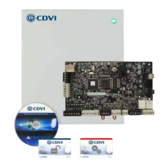
INSTALLATION MANUAL ATRIUM A22 2-Door Controller 3] PACKAGE CONTENTS This chapter details how to install and setup the ATRIUM A22 . The A22 contains: • One A22 module in its cabinet with connection diagram label • AC power cord • Metal Box kit (See below) •... -
Page 8: Location And Mounting
INSTALLATION MANUAL ATRIUM A22 2-Door Controller LOCATION AND MOUNTING The cabinet is designed to be installed indoors, in a safe and secure location. Suggested locations include electrical rooms, communication equipment rooms, closets or in the ceiling. To save time, wiring and facilitate testing, install the cabinets at an equal distance between its controlled doors. -
Page 9: Mounting Instructions
The box needs to be prepared before fixing it to its location. INSTALLING THE TAMPER SWITCHES Installing tamper switches allows the A22 to detect when the cabinet door is opened and/or when the cabinet is removed from the wall. If needed install the tamper switch(es) as follows:... - Page 10 INSTALLATION MANUAL ATRIUM A22 2-Door Controller Install the wall tamper switch using the supplied bolts and nuts as shown in the following picture. Install the tamper switch plastic spacer on the back at bottom left side of Cabinet Side View the box as show in the following picture.
- Page 11 INSTALLATION MANUAL ATRIUM A22 2-Door Controller Install the door tamper switch by aligning the switch holes to the pre-installed plastic bracket pins. Press firmly to secure the tamper switch in position, then fix the bracket to is mounting flange. Refer to page 16 for wiring diagram.
-
Page 12: Installing The Box Lock
INSTALLATION MANUAL ATRIUM A22 2-Door Controller INSTALLING THE BOX LOCK Installing the box lock allows to secure the box from unauthorized access. Installation procedure: Remove the box door knock-out. Insert the lock in the hole. Slide the “U” metal part into the lock groove to secure the lock in place. -
Page 13: Fixing The Box To Its Location
INSTALLATION MANUAL ATRIUM A22 2-Door Controller FIXING THE BOX TO ITS LOCATION Install the box to its location using 4 screws (not supplied) as shown in the following picture. If the wall tamper switch is used, make sure that the tamper switch arm moves freely and is completely pushed in when the enclosure is installed on the wall. -
Page 14: Installing The A22 Pc Board
Install the 5 fasteners (PCB holder) supplied respectively to the box holes identified in red in the following picture. Install the A22 PCB by aligning the fasteners with the corresponding PCB holes and pressing firmly to secure the PCB in place. -
Page 15: Wiring Diagram
5] WIRING DIAGRAM MODULE TYPE CONFIGURATION (CONTROLLER OR EXPANDER) The flexibility of the A22 module allows it to be set either as a 2-door controller or 2-door expander. Simply adjust the “TYPE” jumper to the required position (see the diagram below). -
Page 16: Box Tamper Switches
2-Door Controller BOX TAMPER SWITCHES Connecting the tamper switches allows the A22 to detect when the cabinet door is opened and/or when the cabinet is removed from the wall. To install the tamper switches, see “Installing the Tamper Switches”. LOCAL... -
Page 17: Readers And Keypads
SETTING ETHERNET MODULE TYPE a bright blue backlight in standby mode. A list of other CDVI readers and keypads is shown below. Other SYSTEM STATUS popular wiegand readers and keypads are also supported. Contact us to confirm compatibility. Most readers +12V DC and keypads have built-in buzzers and LEDs. -
Page 18: Inputs
2-Door Controller INPUTS The A22 can monitor the state of up to 6 devices (12 using zone doubling) such as magnetic contacts, motion detectors, temperature sensors, or other devices. The following are examples of the type of inputs that can be... - Page 19 INSTALLATION MANUAL ATRIUM A22 2-Door Controller Input Connection Methods Single without EOL and without TAMPER Supervision INPUTS (Limit of 1 Detection Device on the Input) 12V Z1 GND Z2 Z3 GND Z4 Z5 When using this method, only one device can be connected to the input.
- Page 20 INSTALLATION MANUAL ATRIUM A22 2-Door Controller Single with WIRE SHORT and WIRE CUT Supervision INPUTS (Limit of 1 Detection Device on the Input) 12V Z1 GND Z2 Z3 GND Z4 Z5 When using this method, only one device can be connected to the input.
-
Page 21: Door Lock Devices
INSTALLATION MANUAL ATRIUM A22 2-Door Controller DOOR LOCK DEVICES Each controller has two lock outputs. The LOCK OUTPUT can be configured to provide power (750mA @ 12Vdc), see “Jumper Settings” on this page, the LOCK OUTPUT is protected by a fuseless protection algorithm and will shutdown if the current exceeds 750mA @ 12Vdc. - Page 22 (De-energize lock output) (Energize lock output) INSTALLATION MANUAL ATRIUM A22 LOCAL LOCK 1 LOCK 2 24V DC INPUT ETHERNET STATUS SETTING SETTING BATTERY ETHERNET 2-Door Controller MODULE TYPE SYSTEM STATUS +12V DC INPUT +24V DC RS485 POWER LOCAL SUPPLY Lock Device Wiring Diagram...
-
Page 23: Power Supply
• Real Time Monitoring algorithm for ‘Battery Low/Disconnect/Reversal’ and ‘Insufficient Main Power’. AC Source The AC to DC power supply is pre-installed in the A22 box but needs to be connected to the PCB. Simply plug the two pin terminal to the input power supply. - Page 24 INSTALLATION MANUAL ATRIUM A22 2-Door Controller The Minimum Size Equipment Conductors for the AC mains required are 14 AWG if made of Copper or 12 AWG if made of Aluminium or Copper-Clad Aluminium. Do not use any switch-controlled outlets to power the system.
-
Page 25: Battery Backup
2-Door Controller BATTERY BACKUP The A22 cannot be started on battery power only. Battery backup time varies with each system. Typical backup time is between 2 and 20 hours using standard equipment and settings. Wire a 12Vdc (either 4.5Ah or 7Ah) gel type battery and then connect it to the BATT “+” and “-” terminals with the battery leads supplied. -
Page 26: Led Indicators
The ATRIUM A22 has several status LEDs that are very useful to diagnose problems when using or installing the ATRIUM system. Refer to the following picture to locate the LEDs on the ATRIUM A22. All LEDs are explained in the following pages. -
Page 27: Ethernet
The ATRIUM A22 provides a 10/100Mbps Ethernet port to allow direct connection from a local PC or interconnect to an existing LAN/WAN. Connect the Ethernet 10/100 Mbps port of the ATRIUM A22 to a LAN or WAN network using an UTP cable (maximum 100m (300ft)). -
Page 28: Expander Modules To The Controller
The A22 has a RS485 LOCAL BUS terminal allowing the connection with the ATRIUM expander module. The RS485 LOCAL BUS communication is up to 1220 m (4000 ft) maximum distance. One A22 can support up to four A22 expansion modules. Refer to “Module type configuration (controller or expander)” on page 15 to set an A22 as an expander. -
Page 29: Programming
INSTALLATION MANUAL ATRIUM A22 2-Door Controller 6] PROGRAMMING The stand-alone card enrollment allows you to add or delete user cards without the need of a PC. CARD ENROLLMENT PROCEDURE (ADD OR DELETE CARDS WITHOUT A COMPUTER). Present the MASTER card to a reader. -
Page 30: Warranty - Terms & Conditions
CDVI or a local CDVI subsidiary. The “5 Year Warranty” is only applicable to hidden defects detected during the lifetime of the product, as defined by the CDVI Group (5 years or 200 000 operations - whichever of the two expires first). - Page 31 • Any product which has undergone even the slightest modification or change; • Any product which has been installed and/or used with any auxiliary device not supplied by CDVI; • Any product which has been used for demonstrations or display;...
- Page 32 Reference : G0301EN0413V01 Extranet : EXE-CDVI_IM A22 CMYK A4 EN 01 *G0301EN0413V01* CDVI Group FRANCE (Headquarter/Siège social) Phone: +33 (0)1 48 91 01 02 Fax: +33 (0)1 48 91 21 21 CDVI CDVI FRANCE + EXPORT IBÉRICA Phone: +33 (0)1 48 91 01 02...
Need help?
Do you have a question about the A22 and is the answer not in the manual?
Questions and answers
WHAT PORT NUMBERS NEED TO BE OPEN TO ACCESS YOUR DEVICE REMOTELY THROUGH A ROUTER ?