
Related Manuals for CDVI Centaur CTV900A


Summary of Contents for CDVI Centaur CTV900A
- Page 1 ENGLISH CTV900A 2-Door Controller Range: Online Access Control INSTALLATION MANUAL Group Products...
- Page 2 7] WARRANTY - TERMS & CONDITIONS . . . . . . . . . . . . . . . . . . . . . . . . . . . . . . . . . . . . . . . . . . . . .38 Copyright (C) 2011 CDVI. All rights reserved. CENTAUR Access Control is protected by copyright law and international treaties.
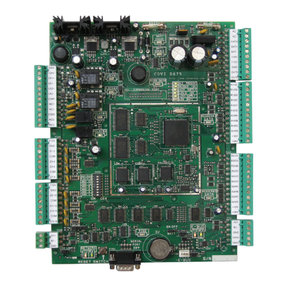
- Page 3 INSTALLATION MANUAL CTV900A 2-Door Controller 1] PRODUCT PRESENTATION The CTV900A is at the heart of every Centaur access control system. The Centaur Server, hardware expansion modules, multi-purpose inputs, card readers, keypads and outputs are connected directly to the CTV900A. Multi-controller systems are networked via the RS485 communication bus (or using the optional CAETHRA over a TCP/IP network).
- Page 4 (1) this device may not cause harmful interference, and (2) this device must accept any interference received including interference that may cause undesired operation. This class A digital apparatus meets all requirements of the Canadian Interference Causing Equipment Regulations. The CENTAUR CTV900A 2-Door Controller is also compliant with EN55022:1998, amendment 1:1995, Class A.
- Page 5 INSTALLATION MANUAL CTV900A 2-Door Controller RECOMMENDED WIRING Maximum Equipment Wire Type Size Length 4 to 8 conductors, stranded, shielded (foil), drain Card reader and 22AWG (0.64mm) to conductor. For example: Alpha 5196, 5198, 5386, 150m (500ft.) 18AWG (1.02mm) Wiegand keypad 5388, Belden 9553 12 conductors, stranded.
- Page 6 7A Fuse, Against reversal Power output specifications Battery Backup Two 12Vdc 7Ah rechargeable acid/lead or gel cell backup battery (UL/ULC: YUASA #NP7-12 Battery Capacity recommended, Europe: CDVI B7AH recommended). Ensure proper polarity. Charging Voltage 27.6V Low Battery @ 21.6Vdc Low Battery Restore @ 24.1Vdc...
- Page 7 INSTALLATION MANUAL CTV900A 2-Door Controller 3] PACKAGE CONTENTS This chapter details how to install and setup the CENTAUR 2-Door Controller. CONTENT OF THE 2-DOOR CONTROLLER The 2-Door Controller contains: • One 2-Door Controller module in its cabinet with connection diagram label •...
- Page 8 INSTALLATION MANUAL CTV900A 2-Door Controller LOCATION AND MOUNTING The cabinet is designed to be installed indoors, in a safe and secure location. Suggested locations include electrical rooms, communication equipment rooms, closets or in the ceiling. To save time, wiring and facilitate testing, install the cabinets at an equal distance between its controlled doors.
- Page 9 INSTALLATION MANUAL CTV900A 2-Door Controller 4] MOUNTING INSTRUCTIONS The box needs to be prepared before fixing it to its location. INSTALLING THE TAMPER SWITCHES Installing tamper switches allows the 2-Door Controller to detect when the cabinet door is opened and/or when the cabinet is removed from the wall.
- Page 10 INSTALLATION MANUAL CTV900A 2-Door Controller INSTALLING THE BOX LOCK Installing the box lock allows to secure the box from non authorized access. If needed install the box lock as shown in the following picture (inside view of the door). Remove the box door knock-out. Insert the lock in the hole.
- Page 11 INSTALLATION MANUAL CTV900A 2-Door Controller FIXING THE BOX TO ITS LOCATION Install the box to its location using 4 screws (not supplied) as shown in the following picture. If the wall tamper switch is used, make sure that the tamper switch arm moves freely and is completely pushed in when the enclosure is installed on the wall.
- Page 12 INSTALLATION MANUAL CTV900A 2-Door Controller INSTALLING THE 2-DOOR CONTROLLER PC BOARD Install the 7 fasteners (PCB holder) supplied respectively to the box holes identified in red in the following picture. cdvigroup.com...
- Page 13 INSTALLATION MANUAL CTV900A 2-Door Controller Install the 2-Door Controller PCB by aligning the fasteners with the corresponding PCB holes and pressing firmly to secure the PCB in place. CTV900A 2-Door Controller cdvigroup.com...
- Page 14 INSTALLATION MANUAL CTV900A 2-Door Controller 5] WIRING DIAGRAM JUMPER SETTINGS Backup battery ON Backup battery OFF ON OFF ON OFF BATT BATT Network EOL ON Network EOL OFF Network A+ & B- HIGH Network A+ & B- LOW HIGH LOW HIGH LOW Lock output 12V Lock output 24V...
- Page 15 INSTALLATION MANUAL CTV900A 2-Door Controller EOL (CONTROLLER NETWORK) Places the EOL termination of the main controller network in circuit (default = off). Jumper should only be on when the controller is the last controller in the network as demonstrated below. “DAISY CHAIN”...
- Page 16 INSTALLATION MANUAL CTV900A 2-Door Controller DIP SWITCH SETTINGS You will found a set of eight dip switches on the lower left hand side of the controller. These dip switches are used to set certain modes in the controller as described below. Changes to the dip switch settings will only be applied when the controller is powered up or if you press the “Reset Switch”...
- Page 17 INSTALLATION MANUAL CTV900A 2-Door Controller Assigning Controller Addresses Via Dip Switches DIP SWITCHES DIP SWITCHES OFF OFF OFF OFF OFF OFF OFF OFF OFF OFF OFF OFF OFF OFF OFF OFF OFF OFF OFF OFF OFF OFF OFF OFF OFF OFF OFF OFF OFF OFF OFF OFF OFF OFF OFF OFF...
- Page 18 INSTALLATION MANUAL CTV900A 2-Door Controller JUMPER AND ADDRESSABLE DIPSWITCH SETTINGS EXAMPLES Example of RS485 controller Example of RS485 controller network using network using a Direct connect configuration CAA360A converter CAA360USBCAB Controller Network At the start point and the end point of the RS485 controller network, the Jumper settings controllers’...
- Page 19 INSTALLATION MANUAL CTV900A 2-Door Controller Example of RS485 E-bus network START POINT At the START POINT and the END POINT of the of the RS485 E-bus network installation, the modules’ EOL jumpers = ON. (Furthest module can be up to All modules in between EOL = OFF 1220m (4000ft) from start point) CTV900A...
- Page 20 INSTALLATION MANUAL CTV900A 2-Door Controller CONNECTING THE ACCESS CONTROL SERVER There are two ways of connecting the controller network to the access control server. If the access control server is located more than 25 feet from the first controller, you will be required to use the CA-360 converter as shown in Figure 1.
- Page 21 INSTALLATION MANUAL CTV900A 2-Door Controller ACCESS CONTROL SYSTEM OVERVIEW For an overview of the access control system using Centaur 4.0 and Up, refer to “Figure 3”. Please take note of the following items concerning the connection of the controller network to the access control server: •...
- Page 22 INSTALLATION MANUAL CTV900A 2-Door Controller Figure 3: Overview of Access Control System Using Centaur 4.0 and Up Remote Site To other remote sites CAA360USBCAB CTV900A RS485 Converter First Controller RS485 Up To 64 Controllers +12V Printer You can have any number of user interfaces Network Connection RS232...
- Page 23 INSTALLATION MANUAL CTV900A 2-Door Controller CONNECTING READERS AND KEYPADS Each CTV900A controller supports up to two readers and two keypads. With some configurations this can be expanded to a maximum of four readers and four keypads. If you are using the Anti-Passback mode, you will be limited to two controlled doors or one entry/exit door.
- Page 24 INSTALLATION MANUAL CTV900A 2-Door Controller PROGRAMMABLE OUTPUTS Most readers and keypads have built-in buzzers and LEDs. These should be connected to controller’s programmable outputs (OUT1 to OUT6) as shown below. These are open collector outputs capable of sinking 25mA with a 10Ω limiting resistor. For information on how to program the outputs, please refer to the Centaur Operator’s Manual.
- Page 25 INSTALLATION MANUAL CTV900A 2-Door Controller CONNECTING THE BOX TAMPER SWITCHES Connecting the tamper switches allows the 2-Door Controller to detect when the cabinet door is opened and/or when the cabinet is removed from the wall. To install the tamper switches, see “Installing the Tamper Switches”. CTV900A To use both switches: 2-Door Controller...
- Page 26 INSTALLATION MANUAL CTV900A 2-Door Controller CONNECTING BELLS Connect the bell(s) and/or siren(s) as follow: Using CTV900A internal power supply Bell and/or Siren (Note: CTV900A internal 12Vdc @ 1A max.) Using external power supply External Power Supply Bell and/or Siren See “Recommended Wiring” section for more information on wiring type, size, and maximum length. cdvigroup.com...
- Page 27 INSTALLATION MANUAL CTV900A 2-Door Controller CONNECTING INPUTS The 2-Door Controller can monitor the state of up to 16 devices (using zone doubling) such as magnetic contacts, motion detectors, temperature sensors, or other devices. The following are examples of the type of inputs that can be monitored: Magnetic Door Contact: Permits supervision of door “status”...
- Page 28 INSTALLATION MANUAL CTV900A 2-Door Controller Examples of Input Connection Methods Single without EOL and without TAMPER Supervision (Limit of 1 Detection Device on the Input) INPUTS When using this method, only one device can be connected to the 12V Z1 GND Z2 Z3 GND Z4 Z5 input.
- Page 29 INSTALLATION MANUAL CTV900A 2-Door Controller DOOR - LOCKING DEVICES Each controller has two lock outputs and each of these outputs is associated to a reader input. Using the lock output jumpers you can set each lock output to provide 12VDC or 24VDC (see “Jumper Settings”). A lock output voltage of 24VDC is recommended for most locking devices.
- Page 30 INSTALLATION MANUAL CTV900A 2-Door Controller Connecting Locking Devices using CAA110P Lock Control Module Door Strike 1 Important Note: Electromagnetic Lock 1 Power Supply Fire alarm contact Fire alarm contact The CAA110P relays are rated at 12VDC, for Lock 1 for Lock 2 therefore, using the appropriate jumper UNLK1 UNLK2...
- Page 31 INSTALLATION MANUAL CTV900A 2-Door Controller POWER CONNECTIONS A 15 amp AC power source with a dedicated breaker and an isolated ground is recommended. Connect a 24VAC, 75VA (maximum) transformer to the controller’s AC terminals and mount it near the cabinet. Wire two 12VDC, 7Ah, gel type batteries in series and then connect them to the BAT+, BAT- terminals with the battery leads supplied (see page 32).
- Page 32 12Vdc 7Ah rechargeable acid/lead or gel cell backup battery (UL/ULC: YUASA #NP7-12 recommended, Europe: CDVI B7AH recommended). Ensure proper polarity. Various (means any type, from any manufacturer that complies with the “Technical Data and securement means” and meets the “Mark of conformity”...
- Page 33 INSTALLATION MANUAL CTV900A 2-Door Controller LED INDICATORS During a battery test, the “BATT CHECK” LED BATT CHECK should be on for four seconds When there is a complete loss of power (no AC or BATT ENABLE battery), the “BATT ENABLE” LED should be off. LED flashes every 750ms in normal operation or MICRO CHECK every 350ms if communication fails.
- Page 34 INSTALLATION MANUAL CTV900A 2-Door Controller DIAGRAMS Connecting Topologies The 2-Door Controller has a RS485 LOCAL BUS terminal allowing the connection with the CENTAUR expander module. The RS485 LOCAL BUS communication is up to 1220 m (4000 ft) maximum of wires. Connect the expander module’s using this topology: DAISY CHAIN NETWORK...
- Page 35 INSTALLATION MANUAL CTV900A 2-Door Controller Controlled Entry and Exit Reader 1 can be assigned as “Entry” and reader 2 as “Exit”, or vice versa. The status of the door is monitored by installing a magnetic door contact (reed switch). Separate wire runs must be installed for each card reader, door contact and door locking device.
- Page 36 INSTALLATION MANUAL CTV900A 2-Door Controller Controlled Entry with Free Exit Entry through two doors can be controlled with one controller by installing a reader/keypad on one side of each door. If the door status is monitored by a door contact (reed switch) then a “request to exit” (REX) device such as a motion detector, push button or floor mat sensor must be used so that the system can differentiate between a door forced open and an authorized exit.
- Page 37 INSTALLATION MANUAL CTV900A 2-Door Controller Turnstile Most types of turnstile equipment on the market are controlled by an unlock control input which is connected to a solenoid. The installation may require additional relays or the use of a CAA110P Lock Control Module. Card reader Turnstile...
- Page 38 The “limited lifetime warranty” is only applicable to hidden defects detected during the lifetime of the product, as defined by the CDVI Group (10 years or 200 000 operations - whichever of the two expires first). The “limited lifetime warranty” conditions shall not modify the sales conditions between CDVI and its customers.
- Page 39 • Any product which has undergone even the slightest modification or change; • Any product which has been installed and/or used with any auxiliary device not supplied by CDVI; • Any product which has been used for demonstrations or display;...
- Page 40 Reference : G0301FR0413V01 Extranet : EXE-CDVI_IM CTV900 CMYK A4 EN 02 Creator of electronic access solutions *G0301FR0413V01* CDVI Group FRANCE (Headquarter/Siège social) Phone: +33 (0)1 48 91 01 02 Fax: +33 (0)1 48 91 21 21 CDVI CDVI CDVI CDVI UK...
Need help?
Do you have a question about the Centaur CTV900A and is the answer not in the manual?
Questions and answers