Table of Contents
Advertisement
Advertisement
Table of Contents

Related Manuals for CDVI CT-V900


Summary of Contents for CDVI CT-V900
- Page 1 CT-V900 Controller Installation Manual...
-
Page 3: Table Of Contents
Mantrap ....................22 www.cdvgroup.com CT-V900 CONTROLLER 3... -
Page 4: System Overview
SYSTEM OVERVIEW SYSTEM REQUIREMENTS POWER REQUIREMENTS • Transformer: 24VAC, 75VA • Backup Battery: Two 12VDC, 7Ah, gel type batteries OPERATOR COMPUTER REQUIREMENTS FOR CENTAUR 2.0 AND 3.0 • Pentium 133MHz (Pentium 200MHz or higher recommended) • Microsoft® Windows® 95/98 or Windows® NT service pack 4.0 or higher • 32MB RAM (64MB Recommended) • 200MB free disk space (300 Recommended) • RS-232 Serial Port • CD-ROM Drive required for installation • Super VGA Monitor ACCESS SERVER COMPUTER REQUIREMENTS FOR CENTAUR 3.0 • Pentium 200MHz (Pentium 300MHz or higher recommended) • Microsoft® Windows® NT service pack 4.0 or higher • 64MB RAM (128MB RAM Recommended) • 300MB free disk space (1GB Recommended) • RS-232 Serial Port (Depending on the installation, more than one may be required) • CD-ROM Drive required for installation • Super VGA Monitor COMPATIBLE READERS AND KEYPADS • CR-R880 Series PosiProx Proximity Reader. -
Page 5: Relay Expansion Module (Ca-A460)
Using the CA-A370 provides higher network isolation from noise, thus greatly increasing communications reliability. The CA-A370 simplifies installation, and makes running an RS-485 network more cost-effective by reducing wiring and installation time. RELAY EXPANSION MODULE (CA-A460) The Model CA-A460 Relay Expansion module provides an additional seven relays to a CT-V900 controller. Up to 2 Plug and Play relay expansion modules can be added to each controller for a total of 16 relays per controller. The relay expansion modules are connected to the controller via an RS-485 E-bus, allowing you to install the relay modules a maximum distance of 1220m/4000ft. from the controller. The module features an activation status LED for each relay, a communication failure LED with an associated output, a 24-hour tamper input and supply monitoring. Removable terminals are optional. ELEVATOR FLOOR CONTROLLER (CA-A480) Connected to the controller’s expansion bus, the CA-A480 can control up to 16 floors. Each of the CA-A480 floor control relays can be interfaced directly with an elevator’s floor control buttons in 2 modes (Non Destination Controlled and Destination Controlled). When using the Non Destination Controlled Mode and a valid card is presented, the appropriate floor control relays will become enabled allowing the card holder to select the desired floor. T he Destination Controlled Mode offers a far superior event trail and user accountability by permitting the card holder to make only one floor selection upon presentation of their card. In this mode an... -
Page 6: Location & Installation
LOCATION & INSTALLATION CONTENTS OF CT-V900 PACKAGE When you receive your CT-V900 controller you should find the following items in your package. If you are missing any items, notify your distributor immediately. • 1 CT-V900 Controller in its cabinet • Backup battery lead wires • EOL resistors for controller inputs (8 X 2.2KΩ and 16 X 1KΩ) • CT-V900 cabinet keys • 2 (8) diodes for the door strikes or locks • Tamper switch and metal bracket LOCATION AND MOUNTING The cabinet is designed to be installed indoors, in a safe and secure location. Suggested locations include electrical rooms, communication equipment rooms, closets or in the ceiling. To save time and wiring and facilitate testing, install the cabinets at an equal distance between its controlled doors. Normal temperature and humidity levels should be maintained. • Cabinet Dimensions: 39cm (15.5”) high, 33cm (13”) wide, 10cm (4”) deep • The Cabinet Can Accommodate: Two 12V, 7Ah, gel cell type batteries and wiring connections 15cm (6”) high, 6cm (2.5”) wide, 10cm (4”) deep... -
Page 7: Connecting Earth Ground
If the “micro check”, “low bat”, “reader 1” and “reader 2” LEDs are flashing in a circular manner, the controller has no firmware and must be updated. The update can be done from the firmware update application which can be downloaded from our web site. For more information refer to the Centaur Operator’s Manual or visit our web site at www.postech.ca. BATTERY INDICATIONS • During a battery test, the “BATT CHECK” LED should be on for four seconds. • When there is a complete loss of power (no AC or battery), the “BATT ENABLE” LED should be off. • When the battery voltage drops below 20.5V the “LOW BATT” LED will flash • If the battery voltage drops to below 16.8V, the controller will shut down after one minute. The “LOW BATT” LED will flash twice as fast (strobe) during this one minute period. www.cdvgroup.com CT-V900 CONTROLLER 7... -
Page 8: Jumper Settings
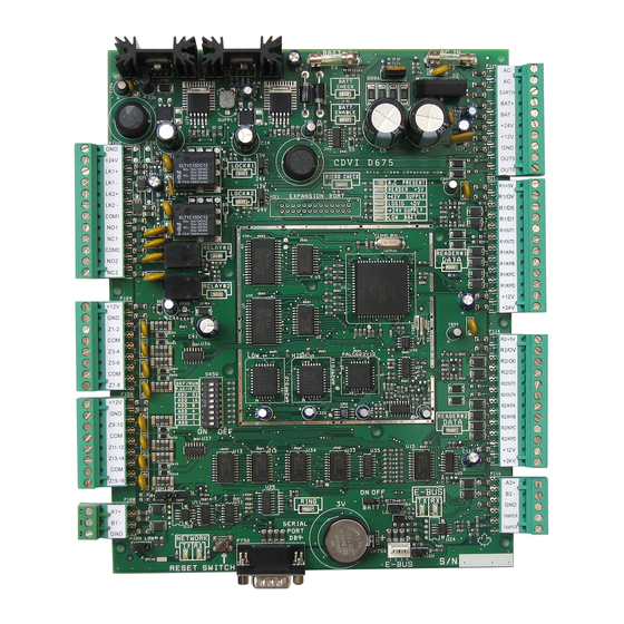
Figure 2: Controller’s Jumper Locations JUMPER SETTINGS As shown in Figure 2 there are nine jumpers used to set some of the controller’s operating modes. BATT ON/OFF When the jumper is on, the controller enables the RAM and RTC battery backup (default = off). Once the controller is installed, the jumper must be on for correct operation. If you are required to replace the 3V backup battery, we recommend that you set the jumper to off until the the battery is replaced. Note however, if a complete power loss occurs, the time and date as well as all controller programming will be lost. EOL (CONTROLLER NETWORK) Places the EOL termination of the main controller network in circuit (default = off). Jumper should only be on when the controller is the last controller in the network as demonstrated in Figure 3. Figure 3: Sample EOL Jumper Settings 12V/24V (LOCK #1) Selects the output voltage of the “LK1+” terminal when the Lock#1 relay is active (default = 12V). When the jumper is on pins 1 & 2 the output will be 12V. If the jumper is on pins 2 & 3 the output will be 24V. 8 INSTALLATION MANUAL www.cdvgroup.com... -
Page 9: 24V (Lock #2)
DEF/RUN DIP SWITCH Set the dip switch to the off (Run) position for normal operation. If you wish to reset the controller to its default settings, set the dip switch to the on (Def) position, then power up the controller or press the “Reset Switch” on the lower left hand side of the controller. Default setting is off (Run). 9.6K/19.2K DIP SWITCH Select the appropriate communications baud rate between the access control server and the network of controllers. Set the dip switch to the on position for 9.6K or set the dip switch to the off position for 19.2K. Default setting is off (19.2K). Verify that the CA-A360 Converter has also been set accordingly. CONTROLLER ADDRESS ASSIGNMENT Each site can manage up to 256 controllers. The 256 controllers are divided into four controller loops of up to 64 controllers each. Using “Table 1” on page 10, set the dip switches to the desired controller address. Each of these loops is assigned to a specific COM port. Controllers connected to the selected COM port will be assigned to a specific address. The access control server (Centaur Software) will recognize these dip switch settings. For more detailed information, please refer to the Centaur Software Manual. www.cdvgroup.com CT-V900 CONTROLLER 9... - Page 10 Table 1: Assigning Controller Addresses Via Dip Switches Cont. Dip Switches Cont. Dip Switches Cont. Dip Switches Add. Add. Add. OFF OFF OFF OFF OFF OFF OFF ON ON OFF ON OFF OFF OFF ON ON OFF ON ON OFF OFF OFF OFF OFF ON OFF ON OFF ON OFF ON ON OFF ON...
-
Page 11: Access Control Network
Figure 5. If the access control server is located less than 25 feet from the first controller, you can connect the access control server directly to the controller’s RS-232 port as shown in Figure 6. The controller then performs the conversion of RS-232 to RS-485 internally. Figure 5: Connecting to the Access Control Server via RS-485 Figure 6: Connecting to the Access Control Server via RS-282 Figure 7: Connecting a Centaur Software Key www.cdvgroup.com CT-V900 CONTROLLER 11... -
Page 12: Access Control System Overview
ACCESS CONTROL SYSTEM OVERVIEW For an overview of the access control system using Centaur 2.0, refer to “Figure 8” on page 12. For an overview of the access control system using Centaur 3.0, refer to “Figure 9” on page 13. Please take note of the following items concerning the connection of the controller network to the access control server: • Centaur 2.0: Up to 16 controllers can be connected to the access control server to control a total of 32 readers. Centaur 3.0: Up to 256 controllers can be connected to the access control server to control a total of 512 readers (expandable to 2048 readers). • Controllers are connected in “daisy chain” format or can be connected in a “star network” when using the CA-A370 Network Hub. “Y” networks cannot be used when connecting the RS-485 communications bus between controllers. • The controller addresses assigned by the dip switches on each controller (see page 9) do not have to correspond to the actual order of controller placement along the RS-485 network. However, we recommend that this is done to facilitate trouble shooting and installation service. • Connect the A1+, B1- and GND of the first controller to the A1+, B1- and GND of the second controller using Belden 1227A type cable. Repeat from the second controller to the third and so forth to a maximum of 1220m (4000 ft.). • Depending on the location of a controller it may be required to place the Controller Network EOL jumper on. For more information refer to “EOL (Controller Network)” on page 8. • To change the communication speed: - stop communications in the CENTAUR software - change the baud rate in the software - change the dip switch settings on all controllers - press the reset button on each board - if using the CA-A360 Converter, change the baud rate jumper (J5) to on - start communications Figure 8: Overview of Access Control System Using Centaur 2.0 12 INSTALLATION MANUAL www.cdvgroup.com... - Page 13 Figure 9: Overview of Access Control System Using Centaur 3.0 www.cdvgroup.com CT-V900 CONTROLLER 13...
-
Page 14: Inputs And Outputs
INPUTS AND OUTPUTS READERS AND KEYPADS Each CT-V900 controller supports up to two readers and two keypads. With some configurations this can be expanded to a maximum of four readers and four keypads. If you are using the Anti-Passback mode, you will be limited to two controlled doors or one entry/exit door. Most Wiegand keypads and readers are connected as shown below. When installing a keypad with a Wiegand output, the keypad’s “D0” and “D1” wires should be connected to the same terminals as the reader’s (the reader output must be open collector). Depending on the required application more than one keypad and/or reader can be connected to the same terminals. -
Page 15: Locking Devices
• When interconnection to a fire alarm system is required, we recommend the CA-A110 Lock Control Module. This module can be used to cut power to the locks during a fire alarm. Refer to the module’s installation instructions for connection of the CA-A110 device. Always consult the regulatory agency in your area for existing regulations regarding doors designated as emergency exits. Figure 11: Connecting Locking Devices Figure 12: Connecting Locking Devices using CA-A110 Lock Control Module www.cdvgroup.com CT-V900 CONTROLLER 15... -
Page 16: Inputs
INPUTS Each controller can monitor the state of up to 16 inputs such as magnetic contacts, motion detectors, temperature sensors or other devices. The following are examples of the type of inputs that can be monitored: Magnetic Door Contact: Permits supervision of door “status” (opened, closed, opened too long, forced open). Inputs 1 and 9 are assigned by default as the door contact of doors 1 and 2 respectively. When using defaults, you can easily swap terminals when troubleshooting. Request for Exit (REX): The device used can be a push button, vertical-view motion detector or floor mat sensor. The door can then be programmed to unlock on a REX detection. Not required if there is a reader/keypad on both sides of the door. When a magnetic door contact is installed, the system can differentiate between a door forced open and an authorized exit. Inputs 2 and 10 (3 and 11 for NC Input Connection above) are, by default, assigned to REX of doors 1 and 2 respectively. Inputs can be installed to a maximum distance of 1000m (3300ft.) from the controller when using AWG #22. Only one of the following input connections can be used per controller (see Figure 13). NC INPUT CONNECTION (8 INPUTS) When using this method, only one device can be connected to each input for a total of eight input devices. All nputs on the selected controller must be connected using the NC Input Connection Method described in Figure 13. This setup will not support tamper and wire fault (short circuit) recognition, but will generate an alarm condition when the state of the input is breached. Only odd numbered inputs (1, 3, 5...) need to be programmed. ATZ 2R CONNECTION (16 INPUTS) This method allows you to connect two devices to each controller input for a total of 16 input devices. All nputs on the selected controller must be connected using the ATZ 2R Input Connection Method described in Figure 13. This setup will not support wire fault (short circuit) recognition, but will generate an alarm condition when the state of the input or its tamper switch is breached. Since an EOL resistor is not installed in this configuration, if the line is cut, a tamper alarm will be generated. ATZ 3R CONNECTION (16 INPUTS) This method allows you to connect two devices to each controller input for a total of 16 input devices. All inputs on the selected controller must be connected using the ATZ 3R Input Connection Method described in... -
Page 17: System Specifications
SYSTEM SPECIFICATIONS RECOMMENDED WIRING CT-V900 CONTROLLER SPECIFICATIONS System Resources Doors: 2 (expandable to 8) Cards: 10,920 (expandable) Schedules: 512 (expandable) Buffered Events: 2048 (expandable) Operating Temperature: 5°C to 55°C (41°F to 133°F) System Autonomy: Full Distributed Architecture (100% Off-line Operation) Firmware: Online Upgradeable Cabinet (Custom Printable): H: 39cm (15.5»), W: 33cm (13»), D: 10cm (4») Elevator Control (Centaur 3.0 only) Controlled Elevators: Floors per Elevator: Schedules per Floor per Elevator: Floor Groups: 128 Inputs Readers: 2 Wiegand or Track 2 Magnetic Swipe Card Readers Keypads: 2 Wiegand and/or BCD Keypads Multi-Purpose Inputs: 8 using N.C. or 16 using ATZ with 2R/3R... - Page 18 On-Board Protection 24VDC: 2.5A Fuseless Protection 12VDC: 1A Fuseless Protection 5VDC: 1A Fuseless Protection AC Protection: 5A Fuse Battery Reversal Protection: 7A Fuse Fuse Failure Indication: Event Generation and LED Display on ALL supplies Battery Backup Battery Capacity: Two 12VDC, 7Ah Low Battery @: 20.5VDC Low Battery Restore @: 23.4VDC Low Battery Cut-Off @: 16.8VDC Outputs Lock Outputs: 2 Outputs: 350mA @12/24VDC Relays: 2 Form «C» Relays: 5A 30VDC Resistive (Expandable to 16 with CA-A460) Programmable Outputs: 6 Open Collector 25mA Sink • Distributed Architecture (100% off-line operation) • Local Anti-passback • Dynamic Memory Adjustment • Operates with all Centaur Software Applications • E-Bus for Plug and Play expansion modules • Ethernet or Network Ready • On-Line Upgradable Firmware • Supports elevator control • Multiple Reader Technology • RS-232 and RS-485 support Maximum Current Combined Maximum Output Volts DC...
-
Page 19: Diagrams
DIAGRAMS SYSTEM DIAGRAM Figure 14: Overview of Controller Connections www.cdvgroup.com CT-V900 CONTROLLER 19... -
Page 20: Controlled Entry And Exit
CONTROLLED ENTRY AND EXIT Reader 1 can be assigned as “Entry” and reader 2 as “Exit”, or vice versa. The status of the door is monitored by installing a magnetic door contact (reed switch). Separate wire runs must be installed for each card reader, door contact and door locking device. With this configuration, a card and/or keypad access code will be required to enter and exit the protected area. Figure 15: Controlled Entry and Exit 20 INSTALLATION MANUAL www.cdvgroup.com... -
Page 21: Controlled Entry With Free Exit
CT-V900 CONTROLLER SPECIFICATIONS Entry through two doors can be controlled with one controller by installing a reader/keypad on one side of each door. If the door status is monitored by a door contact (reed switch) then a “request to exit” (REX) device such as a motion detector, push button or floor mat sensor must be used so that the system can differentiate between a door forced open and an authorized exit. The REX can be programmed for free exit according to a specific schedule, otherwise a “door forced open” event will be generated. Figure 16: Controlled Entry With Free Exit TURNSTILES Most types of turnstile equipment on the market are controlled by an unlock control input which is connected to a solenoid. The installation may require additional relays or the use of a CA-A110 Lock Control Module. Figure 17: Turnstile Configuration www.cdvgroup.com CT-V900 CONTROLLER 21... -
Page 22: Mantrap
MANTRAP This door configuration is used mostly for high security rooms. A mantrap consists of two or more doors, each controlled by a card reader and/or keypad. When a door is opened upon valid access, it is not possible to open the second door, even with a valid card and/or pin number, until both doors are closed. Most of these applications will use a “request to exit” device to exit the protected area (not shown in illustration). Figure 18: Mantrap Configuration WARRANTY The Seller warrants its products to be free from defects in materials and workmanship under normal use for a period of one year. Except as specifically stated herein, all express or implied warranties whatsoever, statutory or otherwise, including without limitation, any implied warranty of merchantability and fitness for a particular purpose, are expressly excluded. Because Seller does not install or connect the products and because the products may be used in conjunction with products not manufactured by Seller. Seller cannot guarantee the performance of the security system. Seller obligation and liability under this warranty is expressly limited to repairing or replacing, at Seller’s option, any product not meeting the specifications. In no event shall the Seller be liable to the buyer or any other person for any loss or damages whether direct or indirect or consequential or incidental, including without limitation,... - Page 23 31, avenue du Général Leclerc - 93500 PANTIN Tél : 33 (0) 1 48 91 01 02 - Fax : 33 (0)1 48 91 21 21 www.cdvgroup.com...
Need help?
Do you have a question about the CT-V900 and is the answer not in the manual?
Questions and answers