Advertisement
Available languages
Available languages
Quick Links
Advertisement

Subscribe to Our Youtube Channel
Related Manuals for CDVI DGM1D


Summary of Contents for CDVI DGM1D
- Page 1 ESPAÑOL ENGLISH DGM1D Controlador Mifare de 1 puerta ® 1-Door Mifare controller/reader system ® Range: Integrated Access Control / Gama: Control de accesos autónomo INSTALLATION MANUAL MANUAL DE INSTALACIÓN Group Products...
- Page 2 - El cable que une el DGM1D con su lector es un - Cable apantallado de 2 pares para una distancia cable apantallado de 2 pares (hasta 2 m) o un máxima de 2 m.
-
Page 3: Montaje
Cómo crear/añadir tags de usuarios (máx. 200 tags) desde el ordenador, guardar copias de seguridad de - Presente el Tag Maestro en el lector para que el DGM1D las bases de datos de usuarios y gestionar listas ne- entre en modo de programación (el LED se iluminará de gras para descargarlas en el programador (y volcarlas color naranja durante 2 segundos). - Page 4 Controlador Mifare de 1 puerta ® 3] KIT DE MONTAJE Arandela T25 Jumpers Varistor Cabeza de lector DGM1D 4] ESQUEMA DE CABLEADO: DGM1D Esquema de jumpers: JP1, JP2 y JP3 QUITADO PUESTO Modo “Lista Modo “Lista Blanca” Negra” Programación de Modo control de código de sitio...
- Page 5 DGM1D de los picos de tensión provocados Autodiagnóstico: durante la activación del mismo Al conectar el DGM1D, el LED naranja del lector se ilumina 4 dispositivo de cierre. segundos para chequear el sistema. Transcurrido ese tiempo, la luz se apaga.
- Page 6 - La distancia máxima entre la interfaz bus y la central DGM1D debe ser de 50 metros. - Al pasar un tag, el número de serie se transmite a la interfaz bus, que se encarga de permitir o denegar el acceso.
- Page 7 MANUAL DE INSTALACIÓN DGM1D Controlador Mifare de 1 puerta ® INTERFAZ BUS (INTBUSDGM1D) Cable de 1 par AWG35 Cable de 1 par AWG35 Alimentación 230V 12 Vac/dc Varistor Cerradura Botón pulsador interior Alimentación común 230V 12 Vac/dc INTERFAZ BUS BORNES...
- Page 8 MANUAL DE INSTALACIÓN DGM1D Controlador Mifare de 1 puerta ® 7] EJEMPLO DE INSTALACIÓN CON INTERFAZ BUS WIEGAND (INTBUSW) INTBUSW (CONTROLADOR DE PUERTA) INTWDGM1 BORNERO DE 5 PUNTOS DE CONEXIÓN: PLACA MADRE - D691 BORNES CORRESPONDENCIAS Alimentación a lector (-) Común de conexión ext.
- Page 9 (26 o 44 bits). de los equipos. - Al pasar el tag por el lector, el - Al usar el DGM1D con su interfaz - La distancia máxima ente el DGM1D número de serie del tag se envía INTWDGM1D asegúrese de colocar el...
- Page 10 MANUAL DE INSTALACIÓN DGM1D Controlador Mifare de 1 puerta ® 8] EJEMPLO: INSTALACIÓN CON FUENTE DE ALIMENTACIÓN Y VENTOSA ARD212 ARD212 BORNES TENSIÓN 12 Vac 12 Vac 7 - 8 0 Vdc 9 - 10 +12 Vdc 230 Vac 230 Vac...
- Page 11 ¿Qué hacer en caso de haber perdido el código de sitio y la contraseña de su central DGM1D? 1 - Conecte el DGM1D al PCV123D a través del cable RS 232. Asegúrese de que tiene el jumper JP1 puesto y el JP2 quitado.
-
Page 12: General Information
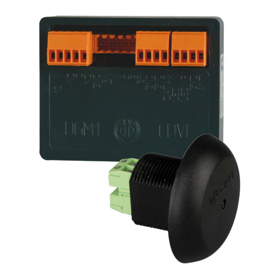
® Dimensions : badges. - DGM1D (L x l x P) = 78 x 57 x 24 mm, - Reader (Ø x P) = Ø44 x 41 mm. Up to 100 doors on the same site: 1 door controller: 1 relay NO/NC. - Page 13 ® Mounting instructions Note: the Master Badge is not deleted. The DGM1D has to be installed in a protected environment compliant to the level 2 of the NF EN 61000-4-4. The wires should not be close Lock time to other source of energy (Ex.: power supply, main...
-
Page 14: Mounting Kit
INSTALLATION MANUAL DGM1D 1-Door Mifare controller/reader system ® 3] MOUNTING KIT T25 Lock-nut Jumpers Varistor Reader DGM1D 4] ELECTRICAL WIRING DIAGRAM Jumpers: JP1, JP2 and JP3 WITHOUT WITH White list Black list mode mode Site code Access control WITH- programming... - Page 15 INSTALLATION MANUAL DGM1D 1-Door Mifare controller/reader system ® Terminal blocks: Voltage: To start your controller you must - Input voltage 12 Volts. at least put the terminals: - Consumption of 300 mA max. DIRECT LINk: - J2: TDG1D, Request to exit input: - J3: Power supply and lock The push button is connected to J5 terminal.
-
Page 16: Important Recommendations
50 meters. - DGM1D time lock is programmable from 2 to 20 seconds with the PCV123D handheld terminal. - If using the DGM1D with the reader interface (INTBUSDGM1), make sure JP2 jumper is ON. GREEN DGM1D... - Page 17 INSTALLATION MANUAL DGM1D 1-Door Mifare controller/reader system ® BUS INTERFACE (INTBUSDGM1D) AWG35 2 pair shielded cable AWG35 2 pair shielded cable Power supply 230V 12V AC or DC Varistor Strike Indoor push button Power supply 230V 12V AC or DC...
- Page 18 INSTALLATION MANUAL DGM1D 1-Door Mifare controller/reader system ® 7] TYPICAL INSTALLATION WITH WIEGAND BUS INTERFACE (INTBUSW) INTBUSW (DOOR CONTROLLER) INTWDGM1 5-POINT TERMINAL BLOCK: MOThER BOARD - D691 TERMINALS DESCRIPTION Power supply - (to reader) Ground Power supply + (to reader)
- Page 19 PCV123D handheld terminal. and bus interface (INTW DGM1D) the reader interface and the (Wiegand 26 or 44 bits). controller unit is 50 meters. - If using the DGM1D with the reader interface (INTBUSDGM1), make sure JP2 jumper is ON. Without jumper...
- Page 20 INSTALLATION MANUAL DGM1D 1-Door Mifare controller/reader system ® 8] EXAMPLE: TYPICAL INSTALLATION WITh A POWER SUPPLY AND AN ELECTROMAGNETIC LOCk ARD212 ARD212 TERMINAL VOLTAGE 12Vac 12Vac 7 - 8 0Vdc 9 - 10 +12Vdc 230Vac 230Vac SYT1 wire 1 pairs 8/10ème SYT1 wire 1 pairs 8/10ème...
- Page 21 3 – PCV123D puts” Incorrect site code” or “Incorrect password”, followed by a decryption string, 4 – Give your decryption string to CDVI support team indicating the controller date (01/01/1998 Date). 5 – CDVI support team will then provide you the controller site code and password.
- Page 22 INSTALLATION MANUAL DGM1D 1-Door Mifare controller/reader system ® 8] NOTES cdviberica.com cdvigroup.com...
- Page 23 INSTALLATION MANUAL DGM1D 1-Door Mifare controller/reader system ® cdviberica.com cdvigroup.com...
- Page 24 Referencia: G0301ES0424V02 Extranet : EXE-CDVI_IM DGM1D CMYk A5 EN-ES 01 Creator of electronic access solutions *G0301ES0424V02* CDVI Group FRANCE (headquarter/Siège social) Phone: +33 (0)1 48 91 01 02 Fax: +33 (0)1 48 91 21 21 CDVI CDVI CDVI CDVI Uk...
Need help?
Do you have a question about the DGM1D and is the answer not in the manual?
Questions and answers