Table of Contents
Advertisement
Advertisement
Table of Contents

Subscribe to Our Youtube Channel
Related Manuals for Metrohm Autosampler plus 919 IC


Summary of Contents for Metrohm Autosampler plus 919 IC
- Page 1 919 IC Autosampler plus Manual 8.919.8003EN / 2020-01-29...
- Page 3 Metrohm AG CH-9100 Herisau Switzerland Phone +41 71 353 85 85 Fax +41 71 353 89 01 info@metrohm.com www.metrohm.com 919 IC Autosampler plus Manual 8.919.8003EN / 2020-01-29...
- Page 4 Technical Communication Metrohm AG CH-9100 Herisau techcom@metrohm.com This documentation is protected by copyright. All rights reserved. This documentation has been prepared with great care. However, errors can never be entirely ruled out. Please send comments regarding possible errors to the address above.
-
Page 5: Table Of Contents
■■■■■■■■■■■■■■■■■■■■■■ Table of contents Table of contents 1 Introduction Area of application ............... 1 Instrument description ............1 Intended use ................. 2 About the documentation ........... 2 1.4.1 Symbols and conventions ............2 Safety instructions ..............3 1.5.1 General notes on safety ............3 1.5.2 Electrical safety ................ - Page 6 ■■■■■■■■■■■■■■■■■■■■■■ Table of contents 4 Operation and maintenance General ................26 Injection valve ..............26 Filter ..................26 Peristaltic pump ..............27 Pump tubings ..............27 5 Troubleshooting Problems and their solutions ..........29 6 Appendix Lift settings ................. 30 Remote interface ..............
- Page 7 ■■■■■■■■■■■■■■■■■■■■■■ Table of figures Table of figures Figure 1 Front 919 IC Autosampler plus ............7 Figure 2 Rear 919 IC Autosampler plus ............8 Figure 3 Connector strip 919 IC Autosampler plus ........... 9 Figure 4 Attaching a sample rack ..............9 Figure 5 Peristaltic pump ................
-
Page 9: Introduction
Dialysis. Thanks to its proven USB interface, the 919 IC Autosampler plus can be integrated into Metrohm instrument systems in a flexible manner. The instrument is always controlled by means of a high-performance PC soft- ware, e.g. MagIC Net™ from Metrohm. -
Page 10: Intended Use
■■■■■■■■■■■■■■■■■■■■■■ 1.3 Intended use Intended use The 919 IC Autosampler plus is designed for usage as an automation sys- tem in analytical laboratories. It is not suitable for usage in biochemical, biological or medical environments in its basic equipment version. The present instrument is suitable for processing chemicals and flammable samples. -
Page 11: Safety Instructions
Electrical safety The electrical safety when working with the instrument is ensured as part of the international standard IEC 61010. WARNING Only personnel qualified by Metrohm are authorized to carry out service work on electronic components. ■■■■■■■■ 919 IC Autosampler plus... -
Page 12: Tubing And Capillary Connections
■■■■■■■■■■■■■■■■■■■■■■ 1.5 Safety instructions WARNING Never open the housing of the instrument. The instrument could be damaged by this. There is also a risk of serious injury if live components are touched. There are no parts inside the housing which can be serviced or replaced by the user. -
Page 13: Personnel Safety
■■■■■■■■■■■■■■■■■■■■■■ 1 Introduction 1.5.4 Personnel safety WARNING Wear protective goggles and working clothes suitable for laboratory work while operating the 919 IC Autosampler plus. It is also advisable to wear gloves when caustic liquids are used or in situations where glass vessels could break. -
Page 14: Recycling And Disposal
■■■■■■■■■■■■■■■■■■■■■■ 1.6 Recycling and disposal Recycling and disposal This product is covered by European Directive 2012/19/EU, WEEE – Waste Electrical and Electronic Equipment. The correct disposal of your old instrument will help to prevent negative effects on the environment and public health. More details about the disposal of your old instrument can be obtained from your local authorities, from waste disposal companies or from your local dealer. -
Page 15: Overview Of The Instrument
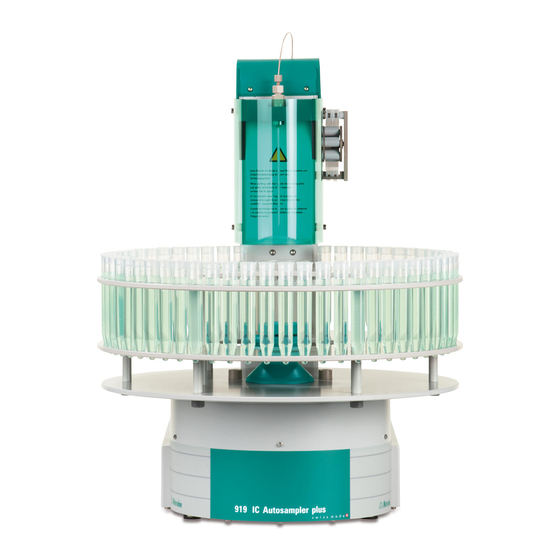
■■■■■■■■■■■■■■■■■■■■■■ 2 Overview of the instrument 2 Overview of the instrument Front Figure 1 Front 919 IC Autosampler plus Safety shield Sample rack (6.2041.510) Peristaltic pump Lift with needle adapter Retaining plate ■■■■■■■■ 919 IC Autosampler plus... -
Page 16: Rear
■■■■■■■■■■■■■■■■■■■■■■ 2.2 Rear Rear Figure 2 Rear 919 IC Autosampler plus Warning symbols Pump connectors (see chapter 1.5.4, page 5) M8 connector for external pumps Stirrer connector 786 Swing Head connector For propeller stirrer (802 Stirrer) and mag- netic stirrer (741 Magnetic Stirrer) Connector strip Details (see chapter 2.3, page 9) ■■■■■■■■... -
Page 17: Connector Strip
P: 115W U: 100 - 240 V f: 50 - 60 Hz MSB 1 For continued protection replace only with the same type and rating of fuse Made by Metrohm Herisau Switzerland USB 2 USB 1 Contr. MSB 2 MSB 3... -
Page 18: Peristaltic Pump
■■■■■■■■■■■■■■■■■■■■■■ 2.5 Peristaltic pump NOTICE After the sample rack has been attached, the rack must be initialized with the Rack initialization function in the control software ("Manual Operation"), so that the magnet code of the rack can be recognized. Automatic recognition of the rack type is only possible when the rack is rotated into the starting position. -
Page 19: Installation
Unplug the power plug immediately if you suspect that moisture has ■ gotten inside the instrument. Only personnel who have been issued Metrohm qualifications may ■ perform service and repair work on electrical and electronic parts. ■■■■■■■■... -
Page 20: Installing The Sample Needle
■■■■■■■■■■■■■■■■■■■■■■ 3.3 Installing the sample needle Connecting the power cord Accessories Power cord with the following specifications: Length: max. 2 m ■ Number of cores: 3, with protective conductor ■ Instrument plug: IEC 60320 type C13 ■ Conductor cross-section 3x min. 0.75 mm / 18 AWG ■... -
Page 21: Figure 6 Installing The Needle
■■■■■■■■■■■■■■■■■■■■■■ 3 Installation Figure 6 Installing the needle PTFE capillary or PEEK capillary PEEK pressure screw 6.1803.070 or 6.1831.050 / 6.1831.060 / 6.2744.070 6.1831.080. Pressure screw Ferrule 4.766.4320 (part of 6.2833.030). Needle holder (6.2833.030) Sample needle 6.2846.010 (made of zirconium oxide) or 6.1835.020 / 6.1835.040 / 6.1835.050 (made of PEEK). -
Page 22: Installing The Peristaltic Pump
■■■■■■■■■■■■■■■■■■■■■■ 3.4 Installing the peristaltic pump Tighten the pressure screw in the needle holder by hand (do not ■ use tools!). 4 Connecting the capillary Slide the 6.2744.070 PEEK pressure screw (6-2) over the end of ■ the capillary. Manually tighten the PEEK pressure screw with the capillary to the ■... - Page 23 ■■■■■■■■■■■■■■■■■■■■■■ 3 Installation Mount the pump tubing as follows: 1 Remove the tubing cartridge Release the tubing cartridge from the cartridge holder by pressing the snap-action lever and unhooking it from the mounting bolts (5-1). 2 Insert the pump tubing Press the contact pressure lever all the way down.
-
Page 24: Figure 8 Inserting The Tubing Cartridge
■■■■■■■■■■■■■■■■■■■■■■ 3.4 Installing the peristaltic pump Figure 8 Inserting the tubing cartridge 6 Connect the capillaries Screw the respective capillaries tightly to the two tubing olives ■ with PEEK pressure screws (7-1). Table 1 Pump tubings and suitable adapters Pump tubing Adapter 6.1826.020 (blue/blue) 6.1826.310 (orange/green) - Page 25 ■■■■■■■■■■■■■■■■■■■■■■ 3 Installation Pump tubing Adapter 6.1826.360 (white/white) 6.1826.380 (gray/gray) 6.1826.390 (yellow/yellow) Setting the flow rate The contact pressure of the tubing cartridge must be adjusted in order to regulate the flow rate. Proceed as follows: 1 Set the contact pressure Fully loosen the contact pressure lever (7-5), i.e.
-
Page 26: Filtration Cell Holder
■■■■■■■■■■■■■■■■■■■■■■ 3.5 Filtration cell holder Filtration cell holder Figure 9 Installing the filtration cell holder The filtration cell holder (6.2057.030) can be mounted on the side wall of the tower, see above. First remove the second and third screws from the bottom on the side wall. -
Page 27: Connecting A Computer
6.2151.000 controller cable, the instrument can be connected directly, either to a USB socket on a computer, to a connected USB hub or to a different Metrohm control instrument. You need administrator rights for the installation of driver software and control software on your computer. -
Page 28: Figure 11 Connecting The Computer
■■■■■■■■■■■■■■■■■■■■■■ 3.7 Connecting a computer you must comply with the procedures specified. The following steps are necessary: 1 Install the software Insert the computer software installation CD and carry out the ■ installation program directions. Exit the program if you have started it after the installation. ■... -
Page 29: Connecting Msb Devices
In order to connect MSB devices, e.g. stirrers or dosing devices, Metrohm instruments are equipped with up to a maximum of four connectors on what is referred to as the Metrohm Serial Bus (MSB). Various kinds of peripheral devices can be connected in sequence (in series, as a "Daisy Chain") at a single MSB connector (8-pin Mini DIN socket) and con-... -
Page 30: Figure 12 Msb Connections
■■■■■■■■■■■■■■■■■■■■■■ 3.8 Connecting MSB devices Stirrer / Ti Stand Remote Box Ti Stand / Stirrer Relay Box Dosino Dosino Dosino Figure 12 MSB connections The control instrument determines which peripheral devices are suppor- ted. NOTICE When connecting MSB devices together, the following must be observed: Only one device of the same type can be used at a single MSB con- ■... -
Page 31: Connecting A Dosing Device
■■■■■■■■■■■■■■■■■■■■■■ 3 Installation 3.8.1 Connecting a dosing device Three dosing devices can be connected to the instrument. The MagIC Net control software supports only the 800 Dosino as a dosing device. 800 Dosino ■ WARNING If a Dosino is connected to the 919 IC Autosampler plus, then the con- nection cable must be equipped with a T.2400.102 ferrite core. -
Page 32: Connecting A Stirrer Or Titration Stand
■■■■■■■■■■■■■■■■■■■■■■ 3.8 Connecting MSB devices 3.8.2 Connecting a stirrer or titration stand You can use the following instruments: These devices have a built-in magnetic stirrer (stirring "from below"): 801 Stirrer ■ 803 Ti Stand ■ This device has no built-in magnetic stirrer (stirring "from above"): 804 Ti Stand with rod stirrer 802 Stirrer ■... -
Page 33: Connecting A Remote Box
Instruments that are controlled via remote lines and/or that send control signals via remote lines can be connected via the 6.2148.010 Remote Box. In addition to Metrohm, other instrument manufacturers also use similar connectors that make it possible to connect different instruments together. -
Page 34: Operation And Maintenance
If the injection valve is blocked, then the channels of the valve can be rinsed with water in the opposite direction. If this is not successful, then the injection valve must be cleaned by a Metrohm service technician. Filter The 6.2821.130 filters (17-2) should be replaced every three months and more frequently with higher backpressure. -
Page 35: Peristaltic Pump
■■■■■■■■■■■■■■■■■■■■■■ 4 Operation and maintenance 2 Inserting the filter Place the filter in the tubing olive and press it flat. ■ 3 Installing the filter screw Screw the filter screw back into the tubing olive. ■ Peristaltic pump The flow rate of the peristaltic pump depends on the drive speed, the con- tact pressure and, above all, the inner diameter of the pump tubing. - Page 36 ■■■■■■■■■■■■■■■■■■■■■■ 4.5 Pump tubings Pump tubing selection Pump tubing can differ in terms of material, diameter and thus flow rate. Different pump tubing is used depending on the application. The following table shows the properties and areas of application of the pump tubings: Table 2 Pump tubings...
-
Page 37: Troubleshooting
■■■■■■■■■■■■■■■■■■■■■■ 5 Troubleshooting 5 Troubleshooting Problems and their solutions Problem Cause Remedy The peristaltic pump Peristaltic pump – Contact Correctly set the contact pressure. is pumping too little. pressure too weak. Peristaltic pump – Pump Replace the pump tubing. tubing defective. ■■■■■■■■... -
Page 38: Appendix
■■■■■■■■■■■■■■■■■■■■■■ 6.1 Lift settings 6 Appendix Lift settings Adjusting the needle position First move the lift to working height. 1 Open the safety shield Loosen the lower two fastening screws of the safety shield using the hexagon key provided, and tip up the safety shield. 2 Loosen the nut Slightly loosen the nut below the lift head using a wrench. -
Page 39: Remote Interface
Pin assignment of remote socket and remote plug The above figure of the pin assignment of a Metrohm remote interface does not only apply for the Remote Box, but also for all Metrohm devices with 25-pin D-Sub remote connectors. Inputs +5 V approx. - Page 40 ■■■■■■■■■■■■■■■■■■■■■■ 6.2 Remote interface The input lines can be scanned with the SCAN command. Outputs Open Collector > 200 ms active = low, inactive = high = 20 mA, V = 40 V +5 V: maximum load = 20 mA The output lines can be set with the CTRL command.
-
Page 41: Technical Specifications
Three 9-pin Mini DIN sockets for connecting dosing devices (Dosino/ MSB1…MSB3 Dosimat), stirrers, etc. USB connectors Two USB Downstream Ports (Type A sockets), each 500 mA, for con- necting Metrohm instruments or USB peripheral devices of other man- ufacturers. Stirrer connector DIN socket Stirring rate 722/802 propeller stirrer: 180…3000 rpm... -
Page 42: Mains Connection
■■■■■■■■■■■■■■■■■■■■■■ 7.4 Mains connection Mains connection Voltage 100…240 V (±10%) Frequency 50…60 Hz Power consump- 115 W tion Fuse 2.0 ATH Ambient temperature Nominal function 5…45 °C range Humidity < 80% (at temperatures under 30 °C) Humidity < 50% (at temperatures under 45 °C) Storage –20…60 °C Humidity <... -
Page 43: Dimensions
■■■■■■■■■■■■■■■■■■■■■■ 7 Technical specifications Dimensions Width 0.28 m Height 0.53 m Depth 0.50 m Material Metal housing, surface-treated Housing Weight (without 1.919.0020: 14.00 kg accessories) ■■■■■■■■ 919 IC Autosampler plus... -
Page 44: Accessories
Internet. You can download this information using the article number as follows: Downloading the accessories list 1 Enter https://www.metrohm.com/ into your Internet browser. 2 Enter the article number (e.g. 919) into the search field. The search result is displayed. -
Page 45: Index
Injection valve ....26 Interface ......31 Computer ......19 Peristaltic pump ....27 Output ....... 32 Dosing device ..... 23 Metrohm Serial Bus MSB, see also Remote Box MSB devices ....... 21 "MSB" ........21 Connect ......25 Power grid ......11 Pin assignment ....
Need help?
Do you have a question about the Autosampler plus 919 IC and is the answer not in the manual?
Questions and answers