Table of Contents
Advertisement
Quick Links
Advertisement
Table of Contents

Related Manuals for Metrohm Eco KF Titrator


Summary of Contents for Metrohm Eco KF Titrator
- Page 1 Eco KF Titrator Product manual 8.1027.8001EN / v4 / 2024-07-01...
- Page 3 Metrohm AG Ionenstrasse CH-9100 Herisau Switzerland +41 71 353 85 85 info@metrohm.com www.metrohm.com Eco KF Titrator Firmware version 57.1027.0009 or higher Product manual 8.1027.8001EN / v4 / 2024-07-01...
- Page 4 Disclaimer Deficiencies arising from circumstances that are not the responsibility of Metrohm, such as improper storage or improper use, etc., are expressly excluded from the warranty. Unauthorized modifications to the product (e.g., conversions or attachments) exclude any liability on the part of the manufacturer for resulting damage and its consequences.
-
Page 5: Table Of Contents
Danger during transport of the product ........8 Design of warning messages ..........8 Meaning of warning signs ........... 9 3 Functional description Eco KF Titrator – Overview ..........10 Function of the components ..........14 3.2.1 Magnetic stirrer ..............14 3.2.2... - Page 6 Table of contents ■■■■■■■■■■■■■■■■■■■■■■ 5 Installation Setup location ..............26 Preparing the assembly ............26 Initial assembly of the cylinder unit ........27 Mounting the support rod ..........29 Replacing the adsorber material ........29 Mounting the volumetric Karl Fischer titration cell ..32 Mounting the bottle unit ...........
- Page 7 ■■■■■■■■■■■■■■■■■■■■■■ Table of contents Cleaning the product surface .......... 108 8 Troubleshooting Resetting the system ............110 9 Disposal 10 Technical specifications 10.1 Ambient conditions ............113 10.2 Energy supply ..............113 10.3 Dimensions ................ 114 10.4 Housing ................114 10.5 Connectors specifications ..........
-
Page 9: Overview
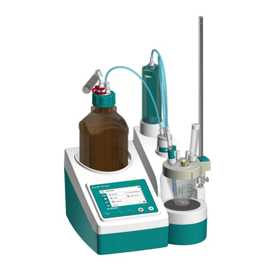
Overview 1 Overview Product description The Eco KF Titrator is an instrument with built-in stirrer used for volumetric water content determination. Conditioning is automatically carried out before and after the actual titration. Reagent dosing is controlled in such a way that a predefined endpoint is reached as quickly and precisely as pos- sible. -
Page 10: Product Versions
Solvent Pump assembly The article number and serial number for identification of the product can be found on the type label: Figure 2 Type label (example) (01) = External article number (21) = Serial number (240) = Metrohm article number ■■■■■■■■... -
Page 11: Displaying Accessories
■■■■■■■■■■■■■■■■■■■■■■ Overview Displaying accessories Up-to-date information on the scope of delivery and on optional accesso- ries can be found on the Metrohm website. 1 Searching for a product on the website Go to https://www.metrohm.com. ■ Click on ■ Enter the article number of the product (e.g. 2.1001.0010) into ■... -
Page 12: Further Information
Metrohm website https://guide.metrohm.com – Documents as PDF, ■ overview of product family, information on applications and details of accessories. Metrohm Knowledge Base https://guide.metrohm.com – Thematically ■ filtered individual content, videos, information on OMNIS Software. About the documentation Possible depictions in the documentation:... -
Page 13: Safety
Safety 2 Safety Intended use Metrohm products are used for the analysis and handling of chemicals. Usage therefore requires the user to have basic knowledge and experience in handling chemicals. Knowledge regarding the application of fire preven- tion measures prescribed for laboratories is also mandatory. -
Page 14: Requirements For Operating Personnel
Always have maintenance work and repairs on electrical components ■ carried out by a regional Metrohm service representative. Disconnect the product from the energy supply immediately if at least ■ one of the following cases occurs: –... -
Page 15: Danger From Highly Flammable Substances
Dispose of chemically contaminated materials (e.g. cleaning material) in ■ accordance with regulations. Proceed as follows in case of a return shipment to Metrohm AG or a ■ regional Metrohm representative: – Decontaminate the product or product component. -
Page 16: Danger During Transport Of The Product
Design of warning messages ■■■■■■■■■■■■■■■■■■■■■■ 2.4.5 Danger during transport of the product Chemical or biological substances may be spilled during the transport of the product. Parts of the product may fall down or may be damaged. There is a risk of injury from chemical or biological substances and pieces of broken glass. -
Page 17: Meaning Of Warning Signs
■■■■■■■■■■■■■■■■■■■■■■ Safety Meaning of warning signs Warning signs on the product or in the documentation indicate potential dangers or draw attention to certain behaviors in order to avoid accidents or damage. Depending on the application purpose, the operating company attaches additional warning signs to the product. -
Page 18: Functional Description
Eco KF Titrator – Overview ■■■■■■■■■■■■■■■■■■■■■■ 3 Functional description Eco KF Titrator – Overview Figure 3 Eco KF Titrator – Front Bottle holder Connector for cylinder unit Flat stopcock Stand attachment Magnetic stirrer Indicators/Controls ■■■■■■■■... - Page 19 ■■■■■■■■■■■■■■■■■■■■■■ Functional description Figure 4 Eco KF Titrator – Rear Type label USB (USB 1 and USB 2) Connect USB flash drive, printer, balance, etc. Ethernet (RJ-45) Remote Remote control via local network Connect remote control Power OUT Power IN...
- Page 20 Eco KF Titrator – Overview ■■■■■■■■■■■■■■■■■■■■■■ Figure 5 Eco KF Titrator – Accessories Cylinder unit Tubing connections Support rod Titration cell Clamping ring Bottle unit ■■■■■■■■...
- Page 21 ■■■■■■■■■■■■■■■■■■■■■■ Functional description Figure 6 Eco KF Titrator – Peripherals Printer Q3X (optional) USB flash drive Ethernet cable (optional) Solvent Pump (optional) Power supply unit ■■■■■■■■...
-
Page 22: Function Of The Components
Function of the components ■■■■■■■■■■■■■■■■■■■■■■ Function of the components 3.2.1 Magnetic stirrer The magnetic stirrer ensures that the sample is well mixed in the reagent. The stirring rate can be adjusted depending on the amount and viscosity of the sample. 3.2.2 Dosing unit Figure 7... - Page 23 ■■■■■■■■■■■■■■■■■■■■■■ Functional description Once the cylinder unit is put into place, the dosing drive and the flat stop- cock assume responsibility for the following functions: Raising and lowering the piston: ■ Solution is aspirated while the piston is being lowered. The dosing cyl- inder fills up.
-
Page 24: Bottle Unit
Function of the components ■■■■■■■■■■■■■■■■■■■■■■ 3.2.2.2 Flat stopcock Figure 9 Flat stopcock – Overview Connector for the tubing connection to Connector for the tubing connection to the bottle the buret tip Connector for the tubing connection to Switching lever the cylinder unit 3.2.3 Bottle unit Figure 10... -
Page 25: Volumetric Karl Fischer Titration Cell
■■■■■■■■■■■■■■■■■■■■■■ Functional description 3.2.4 Volumetric Karl Fischer titration cell Figure 11 Titration cell – Overview Adsorber tube M10 screw nipple (6.02709.010) M12 screw nipple KF titration vessel lid (6.02709.030) Titration vessel Stirring bar Septum stopper Electrode Buret tip The volumetric Karl Fischer titration cell (KF titration cell) is a closed vessel for water content determination according to Karl Fischer and is fastened to the support rod of the magnetic stirrer. -
Page 26: Indicators And Controls
Indicators and controls ■■■■■■■■■■■■■■■■■■■■■■ Indicators and controls Indicators – Status display and status indicator Figure 12 Indicators Status display Status indicator The status indicator is only displayed if the touch screen is switched on. Controls – Control bar Figure 13 Control bar keys On/Off Increase stirring rate... -
Page 27: Remote Interface
Pin assignment of the remote interface Figure 14 Pin assignment of remote socket and remote plug The above figure of the pin assignment applies to all Metrohm instru- ments with 9-pin D-Sub remote connector. Table 5 Inputs and outputs of the remote interface Pin no. - Page 28 Remote interface ■■■■■■■■■■■■■■■■■■■■■■ Pin no. Assignment Function Output 3 Cond. OK Output 4 Error 0 volt (GND) +5 volt Input 0 Start Input 1 Stop Inputs +5 V approx. 5 kΩ Pull-up > 100 ms active = low, inactive = high Outputs Open Collector >...
-
Page 29: Remote Control
An RJ-45 plug with Local Area Network (LAN) is required for this. Connect the Ethernet cable to the Ethernet connector on the rear of the instrument (see "Eco KF Titrator – Overview", chapter 3.1, page 10). The connection can be established only if the instrument and the com-... - Page 30 Remote control ■■■■■■■■■■■■■■■■■■■■■■ Command Function Comment Confirm mes- Confirm the message on the instrument with [OK]. sage A mandatory status scan pro- viding the message number must take place immediately before confirming the mes- sage, see above. $A(OK), $A(CAN- Confirm mes- Confirm the message with CEL) [OK] or [CANCEL].
-
Page 31: Arithmetic Algorithms
■■■■■■■■■■■■■■■■■■■■■■ Functional description Arithmetic algorithms Numerical format The software of the instrument calculates in accordance with the wide- spread standard IEEE 754 (IEEE Standard for Binary Floating-Point Arith- metic for Microprocessor Systems). This means that the numbers are used in calculations in "double precision" (64 bit). Decimal numbers are conver- ted into binary numbers in the computer and used in this form for calcula- tions. - Page 32 Arithmetic algorithms ■■■■■■■■■■■■■■■■■■■■■■ Relative standard deviation (in %): Explanations The individual values are incorporated in the statistics with full accuracy. 15 significant places are yielded when the 64 bit numerical format is applied for the floating-point number in decimal presentation. The accuracy can be controlled by the selection of the prefix of the unit (milli, micro) and the number of decimal places.
-
Page 33: Delivery And Packaging
■■■■■■■■■■■■■■■■■■■■■■ Delivery and packaging 4 Delivery and packaging Delivery Inspect the delivery immediately upon receipt: Check the delivery against the delivery note to ensure completeness. ■ Check the product for damage. ■ If the delivery is incomplete or damaged, contact your regional Met- ■... -
Page 34: Installation
Protect live components (e.g. power supply unit, power cord, con- ■ nection sockets) against moisture. Always have maintenance work and repairs on electrical compo- ■ nents carried out by a regional Metrohm service representative. Connecting the power cord Required accessories: Power supply unit (6.2164.010) ■... -
Page 35: Initial Assembly Of The Cylinder Unit
■■■■■■■■■■■■■■■■■■■■■■ Installation Country-specific cable for power supply, suitable for the power supply ■ unit Figure 16 Rear of the instrument – Connecting the power cord Connect the power supply unit to the Power IN connector. Note the alignment (see figure). 2 Connect the country-specific cable to the power supply unit. - Page 36 Initial assembly of the cylinder unit ■■■■■■■■■■■■■■■■■■■■■■ The instrument is switched on. The push rod is in the lowest position. ■ 1 The installation wizard starts automatically if the instrument is switched on for the first time. The installation wizard can also be started manually with the Man- ▶...
-
Page 37: Mounting The Support Rod
■■■■■■■■■■■■■■■■■■■■■■ Installation Mounting the support rod Mounting the support rod 1 Screw the support rod onto the stand attachment. 2 Push the clamping ring over the support rod with the indent facing upward as far as it will go. The clamping ring is used as the lower stop for the titration vessel lid. - Page 38 Remove the lid by pulling it out of the housing. ■ 2 Removing the adsorber material Remove the entire content. ■ This step is not necessary if the housing is empty. ■ The molecular sieve can be regenerated at 300 °C in the drying oven, see https://www.metrohm.com/en/support-und-service/ faq-kft/. ■■■■■■■■...
- Page 39 ■■■■■■■■■■■■■■■■■■■■■■ Installation 3 Filling the housing with adsorber material Place a cotton plug loosely at the base of the housing. Do not ■ pack the cotton too tightly as sufficient gas flow has to be possi- ble. Fill the housing with molecular sieve to approx. 1 cm under the ■...
-
Page 40: Mounting The Volumetric Karl Fischer Titration Cell
Mounting the volumetric Karl Fischer titration cell ■■■■■■■■■■■■■■■■■■■■■■ At average humidity, we recommend replacing the adsorber mate- rial approx. every 6 weeks. An increase in drift indicates that the leak-tightness of the KF titra- tion cell should be inspected and that the molecular sieve should possibly be replaced. - Page 41 ■■■■■■■■■■■■■■■■■■■■■■ Installation 2 Insert the electrode in the M12 screw nipple on the left and then tighten the screw nipple until it seals. 3 Insert the adsorber tube in the M12 screw nipple on the right and then tighten the screw nipple until it seals. 4 Introduce the septum stopper (with septum inserted) into the front opening of the titration vessel lid.
-
Page 42: Mounting The Bottle Unit
Mounting the bottle unit ■■■■■■■■■■■■■■■■■■■■■■ Mounting the bottle unit Preparing the bottle cap Required accessories: Bottle cap (6.1602.105) ■ Cannula (6.1819.020) ■ Threaded stopper (6.1446.080) ■ Adsorber tube (6.1619.010) ■ Ground-joint clip SGJ 14/15 (6.2023.020) ■ Cotton ■ Suitable sorbent ■... -
Page 43: Mounting The Tubing Connections
■■■■■■■■■■■■■■■■■■■■■■ Installation The bottle unit is mounted Mounting the tubing connections The tubing connections connect the flat stopcock with the bottle unit, the cylinder unit, and the buret tip. Figure 18 Tubing connections Mounting the tubing connections and the buret tip NOTICE Deformation of the screw nipple of the tubing connections. - Page 44 Mounting the tubing connections ■■■■■■■■■■■■■■■■■■■■■■ Required accessories: 2x FEP tubing 31 cm (6.1805.090) ■ 1x FEP tubing 40 cm (6.1805.100) ■ Optional: ■ – Stopper (6.02709.010) 1 Screw the 6.1805.090 tubing securely to the cylinder unit and to the flat stopcock. 2 Screw the 6.1805.090 tubing securely to the bottle unit and to the flat stopcock.
-
Page 45: Operation And Control
■■■■■■■■■■■■■■■■■■■■■■ Operation and control 6 Operation and control Switching the instrument on and off Switching on the device Prerequisite: The power cord is connected. ■ The device is switched off. ■ 1 Press the key. The instrument is initialized and a system test is performed. ▶... -
Page 46: User Interface
User interface ■■■■■■■■■■■■■■■■■■■■■■ Switching off the system Prerequisite: The instrument is switched on. ■ 1 Press and hold down the keys simultaneously until the progress bar is full. If the keys are released during this time, then the instrument will remain switched on. This is to prevent accidental switch- off. - Page 47 The following work areas can be selected: Eco KF Titrator start page The start page with access to the functions: Methods ■...
- Page 48 User interface ■■■■■■■■■■■■■■■■■■■■■■ Live status Access to the graphic display of the ongoing determination. Menu path In the menu path, clicking one of the elements of the menu path can be used to call up the respective menu. Buttons, input fields, keyboards and help texts The menu provides the following possible inputs and information: Buttons ■...
- Page 49 ■■■■■■■■■■■■■■■■■■■■■■ Operation and control Brightness of the display The brightness of the display can be adjusted on the start page in the Sys- ▶ ▶ Diagnosis Display test menu. The most recently set brightness appears when the instrument is switched on. Brightness Input range 1 to 10...
- Page 50 User interface ■■■■■■■■■■■■■■■■■■■■■■ Figure 21 Keyboard (example: lower-case characters) Input field Delete entry Backspace Cancel input (close window) Apply entry Forwards in the input field Backwards in the input field Space Switch keyboard Figure 22 Keyboard (example: numbers) Input field Delete entry Backspace Cancel input (close window)
-
Page 51: Formula Editor
■■■■■■■■■■■■■■■■■■■■■■ Operation and control 6.2.1 Formula editor Figure 23 Formula editor Input field Deleting the entry Backspace Canceling the entry (closing the win- dow) Applying the entry Forwards in the input field Backwards in the input field The formula editor allows for the entry of formulas. The formula editor is equipped with an automatic syntax check. -
Page 52: Manual Control
Manual control ■■■■■■■■■■■■■■■■■■■■■■ order to define the R# to be used, the corresponding number needs to be added manually after "R#". Example: R5 Variables Clicking on [Var] displays a list with additional variables. These variables can either be entered directly into the formula or can be selected from this list and applied with [OK]. -
Page 53: Manual Control - Dosing
■■■■■■■■■■■■■■■■■■■■■■ Operation and control Prepare buret – The cylinder and the tubing of the buret unit are rinsed ■ and filled. Stirrer – Switch the stirrer on and off and set the stirring rate. ■ Installation wizard – Initial installation of the cylinder unit. ■... - Page 54 Manual control ■■■■■■■■■■■■■■■■■■■■■■ 3 Starting the dosing Press the key. The dosed volume is shown on the screen. As soon as the dosing cylinder is empty, the dosing cylinder will ■ be refilled automatically. Dosing continuously (DOS) 1 Selecting the dosing function ▶...
-
Page 55: Exchanging The Cylinder Unit
If you suspect that chemical substances have penetrated the prod- ■ uct, disconnect the product from the energy supply immediately. Then notify the regional Metrohm service representative. Emptying and removing the cylinder unit 1 On the Start... - Page 56 Manual control ■■■■■■■■■■■■■■■■■■■■■■ Make sure that the buret tip points into a vessel. ■ [Continue] ■ The piston rises and the dosing cylinder empties as much as possible. The message Exchanging cylinder unit... appears. Once the push rod has reached the top position, the following warn- ing appears: Make sure that the tubing from the bottle cap is removed.
- Page 57 ■■■■■■■■■■■■■■■■■■■■■■ Operation and control Mounting the cylinder unit Prerequisite: The instrument is switched on. ■ The [Exchange cylinder unit] process was executed up to the point ■ when the cylinder unit can be removed from the instrument. The instrument is carrying out the [Exchange cylinder unit] proce- ■...
-
Page 58: Preparing The Buret (Prep)
Manual control ■■■■■■■■■■■■■■■■■■■■■■ Make sure that the cylinder unit has been mounted correctly. [Continue] 6 [Continue] ▶ Make sure in the System Settings menu that the value of the cyl- inder volume matches the volume of the mounted cylinder unit. The cylinder unit is ready and the Prepare buret (PREP) command... -
Page 59: Operating The Magnetic Stirrer
■■■■■■■■■■■■■■■■■■■■■■ Operation and control The buret is prepared and can be used. 6.3.4 Operating the magnetic stirrer Switching the stirrer on and off Prerequisite: The instrument is switched on. ■ 1 Add a stirring bar to the sample vessel. 2 On the Start page, click on the [Manual control] button. -
Page 60: Methods
Methods ■■■■■■■■■■■■■■■■■■■■■■ ▶ The magnetic stirrer controls are opened: Start page Manual con- ■ ▶ trol Stirrer The stirrer is switched on. ■ 1 Reducing the stirring rate in steps Click repeatedly until the desired stirring rate has been reached. With each click, the stirring rate is reduced by one step. - Page 61 ■■■■■■■■■■■■■■■■■■■■■■ Operation and control Figure 24 Method selection bar Display in the Example Meaning method selection Method name KFT_Ipol The method is saved in the method list. Method name KFT_Ipol The method has just been created. [New] [New] It has not been saved. Method name KFT_Ipol The method has been modified.
-
Page 62: Using And Managing Methods
Methods ■■■■■■■■■■■■■■■■■■■■■■ Figure 25 Method list (example) A scroll bar appears if the list is longer. Titration mode Each method is based on the same titration mode. The corresponding cal- culation is specified in each case. The following titration modes are available: KFT Ipol –... - Page 63 ■■■■■■■■■■■■■■■■■■■■■■ Operation and control Import method – Add a method from a USB flash drive to the ■ method list. Loading the method 1 Open the method selection bar on the Start page: Click on A list with the saved methods appears. The list can be searched with the scroll bar.
- Page 64 Methods ■■■■■■■■■■■■■■■■■■■■■■ 2 Click on the input field. A keyboard appears. 3 Enter the desired name with the keyboard. Finish with [OK]. The name that was entered appears in the method selection bar. The method is now saved in the method list. Creating a new method Start page, click on the [Methods] button.
- Page 65 ■■■■■■■■■■■■■■■■■■■■■■ Operation and control If modifications on the method that was loaded before have not been saved, the following warning appears: Store method: The modifications of the current method have not been saved. Do you want to load the method anyway? [Yes] –...
- Page 66 Methods ■■■■■■■■■■■■■■■■■■■■■■ 4 Confirm deleting: [Delete] The deleted method is no longer available in the method list. Exporting a method 1 Connect the USB flash drive to the instrument. 2 On the Start page, click on the [Methods] button. The method list appears. 3 Select the method that you want to export by clicking on it.
-
Page 67: System - Configuration
[No]: The method will not be imported. ■ System – Configuration The system configuration of the Eco KF Titrator defines the basic, method- independent configuration of the instrument. The following submenus can be found under the [System] button on the... - Page 68 System – Configuration ■■■■■■■■■■■■■■■■■■■■■■ Settings – Basic instrument settings. ■ Solutions ■ Common variables ■ External devices (peripherals) ■ Diagnosis ■ File management ■ Ethernet settings ■ Service ■ About ■ Change password ■ COM port settings ■ ■■■■■■■■...
-
Page 69: System - Settings
■■■■■■■■■■■■■■■■■■■■■■ Operation and control 6.5.1 System – Settings ▶ System Settings Figure 26 System – Settings page 1 Figure 27 System – Settings page 2 User name A user name can be entered for the report. This parameter will only be printed if a user has been defined. - Page 70 System – Configuration ■■■■■■■■■■■■■■■■■■■■■■ Input: max. 10 characters Default value: empty Language Set the dialog language. Dialog type The user dialog can be limited for routine operations. The resetting of the dialog will take effect as soon as you exit the start page. Dialog type Expert (default value) ■...
- Page 71 ■■■■■■■■■■■■■■■■■■■■■■ Operation and control Each time a cylinder unit is attached. ■ All tubing and the cylinder are rinsed with this function. Switch: ■ ■ Default value: ON Beep If Beep is activated, a short acoustic signal sounds in the following cases: When a key is pressed.
- Page 72 System – Configuration ■■■■■■■■■■■■■■■■■■■■■■ 3 Select the desired language from the list. If the desired language is not available, import the language: The user interface is now displayed in the selected language. Setting the date and time Prerequisite: The instrument is switched on. ■...
- Page 73 ■■■■■■■■■■■■■■■■■■■■■■ Operation and control 2 Click on Dialog type to expand the list. 3 Select the Routine dialog type. 4 Exit the System menu. The instrument is now in Routine mode. The availability of the set- tings is restricted. Setting the Expert dialog type Start page, click on the [System] button.
-
Page 74: Managing Solutions
System – Configuration ■■■■■■■■■■■■■■■■■■■■■■ 7 Select the Expert dialog type. All the user settings are available. 6.5.2 Managing solutions ▶ System Solutions Figure 28 Solution list (example) Table 7 Managing the solution list Add a new solution to the list. Solution data see below. Edit the data of the selected solution. - Page 75 ■■■■■■■■■■■■■■■■■■■■■■ Operation and control Figure 29 Solutions – Solution data page 1 Figure 30 Solutions – Solution data page 2 Name The designation of the solution is used for unique identification. Input: max. 24 characters Default value: empty Titer Titer of the solution. Input range –999,999,999 to 9,999,999,999 Default value...
- Page 76 System – Configuration ■■■■■■■■■■■■■■■■■■■■■■ Selection: µmol/mL ■ mmol/L ■ mol/L ■ ■ mg/L ■ mg/mL ■ µg/L ■ ■ ■ mEq/L ■ empty ■ User-defined ■ A user-defined unit can be created. This will be added to the selection list. The previous entry will be overwritten as soon as the new unit has been defined.
-
Page 77: Managing Common Variables
■■■■■■■■■■■■■■■■■■■■■■ Operation and control When you start a method, you will be notified if this time interval (in days) has already elapsed. You can then select whether or not you would still like to start the method. 1 to 999 d Input range 999 d Default value... -
Page 78: Managing External Devices
System – Configuration ■■■■■■■■■■■■■■■■■■■■■■ 6.5.4 Managing external devices ▶ System External devices PC/LIMS report Specification of the storage location for the PC/LIMS report. The PC/LIMS report is a machine-readable report with all of the important data for a determination. It can be saved as follows: as a TXT file on a USB flash drive. -
Page 79: System - File Management
■■■■■■■■■■■■■■■■■■■■■■ Operation and control Balance Selection: Sartorius ■ Mettler ■ For balances with RS-232 interface: Use the 6.2148.050 USB/RS-232 Con- verter. ▶ System COM port settings Configure the serial interface: The parameters set for the RS-232 interface on the balance must match those on the instrument. - Page 80 System – Configuration ■■■■■■■■■■■■■■■■■■■■■■ Importing a method 1 Connect the USB flash drive to the instrument. Start page, click on the [System] button. Move to page 2 2 On the and click on [File management]. A list with the methods saved on the USB flash drive appears. 3 Select the method that you want to import by clicking on it.
- Page 81 ■■■■■■■■■■■■■■■■■■■■■■ Operation and control 2 On the Start page, click on the [System] button. Move to page 2 and click on [File management]. A list with the methods saved on the USB flash drive appears. 3 Select the method that you want to delete by clicking on it. The selected method is highlighted in green.
- Page 82 System – Configuration ■■■■■■■■■■■■■■■■■■■■■■ 2 On the Start page, click on the [System] button. Move to page 2 and click on [File management]. 3 Restore the system: A list with the backups saved on the USB flash drive appears. The file names of the backups are structured as follows: SF_YYYY- MM-DD_hhmmss.ods 4 Click on the desired backup.
-
Page 83: Instrument Diagnosis
■■■■■■■■■■■■■■■■■■■■■■ Operation and control 6.5.6 Instrument diagnosis Figure 32 System menu – Diagnosis Display test The [Display test] button offers settings for brightness, various test images and a calibration program for the screen: Figure 33 Display – Controls Menu path Reduce brightness Increase brightness Brightness... -
Page 84: Ethernet Settings
System – Configuration ■■■■■■■■■■■■■■■■■■■■■■ Starts the calibration program. Look at the screen in such a way that your line of ■ sight is vertical to the screen. A crosshair appears in succession at various places on ■ the screen. Each time, click in the center of the cross- hair. -
Page 85: Service - Brief Description
■■■■■■■■■■■■■■■■■■■■■■ Operation and control 6.5.8 Service – Brief description The [Service] button leads to a protected area to which only regional Metrohm service representatives have access. 6.5.9 Changing the password With the password for the Expert dialog type, you can control access to... - Page 86 System – Configuration ■■■■■■■■■■■■■■■■■■■■■■ Selection: 1200 ■ 2400 ■ 4800 ■ 9600 ■ 19200 ■ 38400 ■ 57600 ■ 115200 ■ Default value: 9600 Data bits Number of data bits. Selection: ■ ■ Default value: 8 Stop bits Number of stop bits. Selection: ■...
-
Page 87: Displaying System Data
■■■■■■■■■■■■■■■■■■■■■■ Operation and control Selection: Hardware ■ Software ■ none ■ Default value: Hardware If communication problems occur, set the parameter Handshake to Software, and make another attempt. 6.5.11 Displaying system data ▶ System About menu path shows detailed information on: Program version ■... -
Page 88: Carrying Out The Determination
Carrying out the determination ■■■■■■■■■■■■■■■■■■■■■■ Carrying out the determination 1 Loading the method Load the desired method. ■ 2 Starting conditioning Prerequisite: The titration cell is filled with reagent. ■ Press the key. ■ Conditioning starts. Conditioning not OK is displayed until the ■... - Page 89 ■■■■■■■■■■■■■■■■■■■■■■ Operation and control Figure 35 Live status The axes are scaled automatically. Pauses the determination. Continues the determination. This button appears as soon as the determination is paused. 6 Making live modifications (if necessary) Edit the sample data of the running determination ■...
- Page 90 Carrying out the determination ■■■■■■■■■■■■■■■■■■■■■■ 2 Editing the sample data Edit the sample data. ■ 3 Opening the Live status work area Click on ■ Live status work area appears again. If the determination is finished while an editing dialog is opened (e.g.
-
Page 91: Results
■■■■■■■■■■■■■■■■■■■■■■ Operation and control Increase the stirring rate in steps: ■ Reduce the stirring rate in steps: ■ Results Results shows the work area. Results After a titration has been completed, the work area opens auto- matically. Figure 36 Results overview The results overview shows the calculated results and the stop criterion: Click on the desired result row or stop criterion row. - Page 92 Results ■■■■■■■■■■■■■■■■■■■■■■ Recalculating By clicking on the key, the current determination is recalculated. The procedure will be executed immediately. Recalculation cannot be undone. All the results of the determination that was carried out last are recalcula- ted with the Recalc function.
- Page 93 ■■■■■■■■■■■■■■■■■■■■■■ Operation and control The mean value Mean, the absolute standard deviation s abs and the rel- ative standard deviation s rel are displayed in the overview. For the mean value, the number of individual results from which it has been calculated is displayed in parentheses.
-
Page 94: Printing Reports
Printing reports ■■■■■■■■■■■■■■■■■■■■■■ Printing reports The following reports can be printed out: Results Result report with determination properties, sample data, calculated results, etc. Parameter Report with all method parameters of the loaded method. System System report with system settings, solution list, external devices, etc. Preparing to print ▶... -
Page 95: Parameters
■■■■■■■■■■■■■■■■■■■■■■ Operation and control Parameters Figure 37 Parameters – Menu page 1 Figure 38 Parameters – Menu page 2 6.9.1 Karl Fischer titration volumetric 6.9.1.1 Conditioning ▶ Parameters Conditioning The conditions required for conditioning are defined under [Condition- ing]. Conditioning If this parameter is activated, the first time the titration is started the work- ing medium will be titrated to the endpoint with the specified control parameters. - Page 96 Parameters ■■■■■■■■■■■■■■■■■■■■■■ begin until [START] is pressed once more. Conditioning will be carried out again automatically after the titration. Selection: ■ ■ Default value: ON Start drift Conditioning OK will be displayed as soon as the value falls below this volume drift and the titration can be started.
- Page 97 ■■■■■■■■■■■■■■■■■■■■■■ Operation and control Cond. stop volume Maximum permissible volume that can be dosed during conditioning. Conditioning is stopped when the specified volume is dosed. If condition- ing is continued by pressing [START] once again, then the titrant volume that has already been dosed will not be taken into account; i.e. the dosing starts again at zero.
- Page 98 Parameters ■■■■■■■■■■■■■■■■■■■■■■ Input range 0.01 to 166.00 mL/min Default value Max. mL/min Additional selection: Max. = maximum dosing rate. Default value: Max. The maximum dosing rate depends on the cylinder volume (see table). If volatile solvents/solutions or solutions with a high viscosity are used, the dosing rate must be reduced accordingly so that the cylin- der unit is not overloaded.
- Page 99 ■■■■■■■■■■■■■■■■■■■■■■ Operation and control Request sample unit If this parameter is activated, then the unit for the sample size will be requested at the start of the determination. Switch: ■ ■ Default value: OFF Hold at request If this parameter is activated, then the run will be paused during the request.
- Page 100 Parameters ■■■■■■■■■■■■■■■■■■■■■■ Selection: ■ ■ ■ ■ Default value: 50 μA Electrode test In the case of polarizable electrodes, an electrode test can be carried out. A check is made that the electrode is properly connected and that no short-circuit is present. The electrode test is carried out when the determi- nation is started.
- Page 101 ■■■■■■■■■■■■■■■■■■■■■■ Operation and control Extraction time Minimum duration of the titration. The titration will not be canceled dur- ing the extraction time, even if the endpoint has already been reached. The titration is, however, canceled if a (see "Stop conditions", chapter 6.9.1.5, page 96) is fulfilled during this time.
- Page 102 Parameters ■■■■■■■■■■■■■■■■■■■■■■ The individual titration parameters can be modified. The settings of the individual titration rates are listed below. Table 9 Default values of the predefined titration rates for KFT Titration rate slow optimal fast Control range 300 mV 100 mV 30.0 mV Max.
- Page 103 ■■■■■■■■■■■■■■■■■■■■■■ Operation and control Cylinder volume maximum dosing rate / filling rate 20 mL 60.00 mL/min 50 mL 150.00 mL/min Independent of the cylinder volume, values ranging from 0.01 to 166.00 mL/min can always be entered. When the function is carried out, the rate will be reduced automatically if necessary to the high- est possible value.
- Page 104 Parameters ■■■■■■■■■■■■■■■■■■■■■■ The titration is canceled if the value is below both the endpoint and the sum of the drift at the start of the titration and the relative stop drift. The titration will not be canceled until the stop conditions are fulfilled. Stop drift Stop criterion = Drift.
- Page 105 ■■■■■■■■■■■■■■■■■■■■■■ Operation and control Input range 0.00000 to 9,999.99 mL Default value 100.000 mL Selection: off Stop time The titration is canceled when the specified time has elapsed following the termination of the start conditions. Input range 0 to 999,999 s Default value Selection: off Filling rate...
- Page 106 Parameters ■■■■■■■■■■■■■■■■■■■■■■ Factor (FCT) If a larger amount of solvent is used for determining the blank value than will be used afterwards for the sample, the endpoint volume has to be converted accordingly with this factor. Input range –999,999,999 to 9,999,999,999 Default value Decimal places Number of decimal places used to display the result.
- Page 107 ■■■■■■■■■■■■■■■■■■■■■■ Operation and control Factor (FCT) Conversion factor, see table above. Input range –999,999,999 to 9,999,999,999 Default value Decimal places Number of decimal places used to display the result. Input range 0 to 5 Default value Result unit The result unit is displayed and saved along with the result. Selection: ■...
- Page 108 Parameters ■■■■■■■■■■■■■■■■■■■■■■ Result unit Sample size Factor (FCT) Divisor (DIV) in … Density of the sample in g/mL 1,000 1,000 Density of the sample in g/mL mg/mL Density of the sample in g/mL mg/mL mg/piece Pieces Factor (FCT) Conversion factor, see table above. Input range –999,999,999 to 9,999,999,999 Default value...
- Page 109 ■■■■■■■■■■■■■■■■■■■■■■ Operation and control Selection: ■ ■ mg/mL ■ ■ ■ ■ mg/piece ■ User-defined ■ Default value: % User-defined A user-defined unit can be created. This will be added to the selection list. As soon as a new unit is defined, the previous entry will be overwritten. An empty entry can be generated this way as well.
- Page 110 Parameters ■■■■■■■■■■■■■■■■■■■■■■ Factor (FCT) Conversion factor, see table above. Input range –999,999,999 to 9,999,999,999 Default value Divisor (DIV) Conversion factor, see table above. Input range –999,999,999 to 9,999,999,999 Default value Titer Titer of the solution used. If a solution is selected in Titration parame- ▶...
- Page 111 ■■■■■■■■■■■■■■■■■■■■■■ Operation and control Selection: ■ ■ mg/mL ■ ■ ■ ■ mg/piece ■ User-defined ■ Default value: % User-defined A user-defined unit can be created. This will be added to the selection list. As soon as a new unit is defined, the previous entry will be overwritten. An empty entry can be generated this way as well.
-
Page 112: Maintenance
Metrohm recommends having the products maintained by specialist ■ personnel of Metrohm AG as part of an annual service. Shorter mainte- nance intervals may be necessary if you frequently work with caustic and corrosive chemicals. - Page 113 If you suspect that chemical substances have penetrated the prod- ■ uct, disconnect the product from the energy supply immediately. Then notify the regional Metrohm service representative. Taking the cylinder unit apart Prerequisite: The cylinder unit has been disassembled: (see "Emptying and removing...
- Page 114 Performing maintenance on the cylinder unit ■■■■■■■■■■■■■■■■■■■■■■ Lift the piston carefully out of the dosing cylinder. Use the 6.1546.040 piston tool to accomplish this. The individual parts can now be cleaned and checked. Cleaning the disassembled cylinder unit Prerequisite: The cylinder unit has been taken apart. ■...
- Page 115 ■■■■■■■■■■■■■■■■■■■■■■ Maintenance Lint-free cloth ■ 1 Greasing the piston Grease the piston. ■ Using your finger, carefully apply a trace of paraffin grease ■ (6.2803.010) to the exterior of the sealing lips (orange marking) of the piston. Wipe off excess grease with the lint-free cloth. ■...
-
Page 116: Cleaning The Product Surface
Protect live components (e.g. power supply unit, power cord, con- ■ nection sockets) against moisture. Always have maintenance work and repairs on electrical compo- ■ nents carried out by a regional Metrohm service representative. Prerequisite: The product is switched off and disconnected from the energy supply. ■ Required accessories: Cleaning cloth (soft, lint-free) ■... - Page 117 ■■■■■■■■■■■■■■■■■■■■■■ Maintenance 2 Wipe the surface with a dry cloth. 3 Clean the connectors with a dry cloth. ■■■■■■■■...
-
Page 118: Troubleshooting
The instrument will be reset to factory settings. The pass- word for the Expert dialog type is then: METROHM9100 Metrohm recommends creating a backup of the system at regular intervals in order to avoid data losses. The program version does not change when resetting the system. Resetting the system Prerequisite: The instrument is switched off. - Page 119 ■■■■■■■■■■■■■■■■■■■■■■ Troubleshooting Press the 3 keys simultaneously and hold them down ■ for approx. 4 s. The Factory reset warning appears: All information (including saved methods, determination results, etc.) is deleted. Do you want to con- tinue? 2 Confirming the reset Confirm the warning with [Continue].
-
Page 120: Disposal
■■■■■■■■■■■■■■■■■■■■■■ 9 Disposal Properly dispose of chemicals and of the product to reduce negative effects on the environment and public health. Local authorities, waste dis- posal companies or dealers provide more detailed information on disposal. Observe the WEEE EU directive (WEEE = Waste Electrical and Electronic Equipment) for the proper disposal of waste electronic equipment within the European Union. -
Page 121: Technical Specifications
■■■■■■■■■■■■■■■■■■■■■■ Technical specifications 10 Technical specifications 10.1 Ambient conditions Nominal function range +5 to +45 °C at max. 80% relative humidity, non- condensing Storage +5 to +45 °C at max. 80% relative humidity, non- condensing 10.2 Energy supply External power supply unit Input Nominal voltage range 100–240 VAC... -
Page 122: Dimensions
Dimensions ■■■■■■■■■■■■■■■■■■■■■■ Current at the power supply unit 500 mA max. output current per channel Protection Internal fuse 1.5 A 10.3 Dimensions Measurements Width 286 mm Height without cylinder unit 220 mm with cylinder unit 358 mm with support rod 508 mm Depth 286 mm... -
Page 123: Connectors Specifications
■■■■■■■■■■■■■■■■■■■■■■ Technical specifications 10.5 Connectors specifications Power IN Socket Round plug 4-pin Power OUT Socket Round plug 4-pin Remote Socket D-Sub 9-pin Ethernet CAT 6 Type Socket RJ-45 Cable type min. FFTP shielded Cable length max. 10 m Type Socket Type A Cable type shielded... -
Page 124: Display Specifications
Display specifications ■■■■■■■■■■■■■■■■■■■■■■ 10.6 Display specifications Display Type VGA color display Size approx. 4.3" diagonal Resolution 480 × 272 pixels Status display green 10.7 Operation specifications Touch screen Type resistive Resistance to chemicals Ethanol Methanol Water Keys 5 keys 10.8 Measurement specifications Polarizer Ipol DC... -
Page 125: Stirrer Specifications
■■■■■■■■■■■■■■■■■■■■■■ Technical specifications 10.9 Stirrer specifications Version magnetic Rotational speed range +1 to +15 120–1,800 rpm Rotational speed change per step 115–125 rpm Maximum rotational speed 1,700–1,900 rpm Lengths of stirring bar The stirrer is designed for stirring bars in the following lengths: 8 mm ■...
Need help?
Do you have a question about the Eco KF Titrator and is the answer not in the manual?
Questions and answers