Table of Contents
Advertisement
Advertisement
Table of Contents

Related Manuals for Metrohm Titrando 851


Summary of Contents for Metrohm Titrando 851
- Page 1 851 Titrando Manual 8.851.8004EN / 2020-02-11...
- Page 3 Metrohm AG CH-9100 Herisau Switzerland Phone +41 71 353 85 85 Fax +41 71 353 89 01 info@metrohm.com www.metrohm.com 851 Titrando Manual 8.851.8004EN / 2020-02-11...
- Page 4 Technical Communication Metrohm AG CH-9100 Herisau techcom@metrohm.com This documentation is protected by copyright. All rights reserved. This documentation has been prepared with great care. However, errors can never be entirely ruled out. Please send comments regarding possible errors to the address above.
-
Page 5: Table Of Contents
■■■■■■■■■■■■■■■■■■■■■■ Table of contents Table of contents 1 Introduction The Titrando system ............. 1 Instrument description ............2 Titration modes – Measuring modes – Dosing com- mands ..................2 About the documentation ........... 3 1.4.1 Symbols and conventions ............3 Safety instructions .............. - Page 6 Indicator electrode ..............41 5 Operation and maintenance General notes ..............42 5.1.1 Care ..................42 5.1.2 Maintenance by Metrohm Service .......... 42 Generator electrode ............43 5.2.1 Generator electrode without diaphragm ........ 43 5.2.2 Generator electrode with diaphragm ........43 6 Troubleshooting General ................
- Page 7 ■■■■■■■■■■■■■■■■■■■■■■ Table of contents 8.1.3 Temperature ................51 Power connection ............... 52 Ambient temperature ............52 Interfaces ................52 9 Accessories Index ■■■■■■■■ 851 Titrando...
- Page 8 ■■■■■■■■■■■■■■■■■■■■■■ Table of figures Table of figures Figure 1 The Titrando system ................1 Figure 2 Front 851 Titrando ................7 Figure 3 Rear 851 Titrando ................8 Figure 4 Connecting the Touch Control ............10 Figure 5 Connecting the computer ..............12 Figure 6 MSB connections ................
-
Page 9: Introduction
■■■■■■■■■■■■■■■■■■■■■■ 1 Introduction 1 Introduction The Titrando system The Titrando is the heart of the modular Titrando system. Operation is car- ried out either by a Touch Control with a touch-sensitive screen ("stand- alone titrator") or by a computer with a corresponding software. A Titrando system can contain numerous, various kinds of instruments. -
Page 10: Instrument Description
Operation is carried out by means of a touch-sensitive Touch Control or with a high-performance PC software. MSB connectors ■ Four MSB connectors (Metrohm Serial Bus) for connecting dosing devi- ces (Dosimat with exchange unit or Dosino with dosing unit), stirrers, titration stands and Remote Boxes. USB connectors ■... -
Page 11: About The Documentation
■■■■■■■■■■■■■■■■■■■■■■ 1 Introduction ■ Coulometric bromine index determination. Determining the amount of double bonds in e.g. mineral oils. Measuring mode: – Ipol (voltametric measurement with selectable polarization cur- rent) MEAS ■ The following measuring modes can be selected for measurements: –... -
Page 12: Safety Instructions
1.5.2 Electrical safety The electrical safety when working with the instrument is ensured as part of the international standard IEC 61010. WARNING Only personnel qualified by Metrohm are authorized to carry out service work on electronic components. ■■■■■■■■ 851 Titrando... -
Page 13: Working With Liquids
■■■■■■■■■■■■■■■■■■■■■■ 1 Introduction WARNING Never open the housing of the instrument. The instrument could be damaged by this. There is also a risk of serious injury if live components are touched. There are no parts inside the housing which can be serviced or replaced by the user. -
Page 14: Flammable Solvents And Chemicals
■■■■■■■■■■■■■■■■■■■■■■ 1.5 Safety instructions 1.5.4 Flammable solvents and chemicals WARNING All relevant safety measures are to be observed when working with flammable solvents and chemicals. Set up the instrument in a well-ventilated location (e.g. fume cup- ■ board). Keep all sources of flame far from the workplace. ■... -
Page 15: Overview Of The Instrument
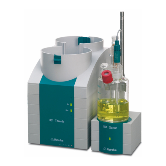
■■■■■■■■■■■■■■■■■■■■■■ 2 Overview of the instrument 2 Overview of the instrument G e n . 8 5 1 T it r a n Figure 2 Front 851 Titrando Bottle holder "On" LED With holding clamps, for two reagent bot- Lights up when the Titrando is ready for tles. -
Page 16: Figure 3 Rear 851 Titrando
USB Sample Processor, etc. Connector (Controller) MSB connector (MSB 1 to MSB 4) For connecting a Touch Control or a PC with Metrohm Serial Bus. For connecting external installed PC software. Mini DIN, 9-pin. dosing devices, stirrers or Remote Boxes. Mini DIN, 9-pin. -
Page 17: Setting Up The Instrument
■■■■■■■■■■■■■■■■■■■■■■ 3 Installation 3 Installation Setting up the instrument 3.1.1 Packaging The instrument is supplied in protective packaging together with the sepa- rately packed accessories. Keep this packaging, as only this ensures safe transportation of the instrument. 3.1.2 Checks Immediately after receipt, check whether the shipment has arrived com- plete and without damage by comparing it with the delivery note. -
Page 18: Figure 4 Connecting The Touch Control
■■■■■■■■■■■■■■■■■■■■■■ 3.2 Connecting a controller 3.2.1.1 Connecting a Touch Control NOTICE The plug is protected against accidental disconnection of the cable by means of a pull-out protection feature. If you wish to pull out the plug, you first need to pull back the outer plug sleeve marked with arrows. Connect the Touch Control as follows: Insert the plug of the Touch Control connection cable into the ■... - Page 19 Using a 6.2151.000 con- troller cable, the instrument can be connected directly, either to a USB socket on a computer, to a connected USB hub or to a different Metrohm control instrument.
-
Page 20: Figure 5 Connecting The Computer
■■■■■■■■■■■■■■■■■■■■■■ 3.2 Connecting a controller 6 .2 1 5 1 .0 0 0 Figure 5 Connecting the computer The instrument is recognized. Depending on the version of the Win- dows operating system used, the driver installation proceeds differ- ently afterwards. Either the necessary driver software is installed automatically or an installation wizard is started. -
Page 21: Connecting Msb Devices
In order to connect MSB devices, e.g. stirrers or dosing devices, Metrohm instruments are equipped with up to a maximum of four connectors on what is referred to as the Metrohm Serial Bus (MSB). Various kinds of peripheral devices can be connected in sequence (in series, as a "Daisy Chain") at a single MSB connector (8-pin Mini DIN socket) and con-... -
Page 22: Connecting A Dosing Device
■■■■■■■■■■■■■■■■■■■■■■ 3.3 Connecting MSB devices NOTICE When connecting MSB devices together, the following must be observed: Only one device of the same type can be used at a single MSB con- ■ nector at one time. Dosing devices of the 700 Dosino and 685 Dosimat plus type cannot ■... -
Page 23: Connecting A Stirrer Or Titration Stand
■■■■■■■■■■■■■■■■■■■■■■ 3 Installation Figure 7 Connecting a dosing device 3.3.2 Connecting a stirrer or titration stand You can use the following instruments: These devices have a built-in magnetic stirrer (stirring "from below"): 801 Stirrer ■ 803 Ti Stand ■ This device has no built-in magnetic stirrer (stirring "from above"): 804 Ti Stand with rod stirrer 802 Stirrer ■... -
Page 24: Connecting A Remote Box
Instruments that are controlled via remote lines and/or that send control signals via remote lines can be connected via the 6.2148.010 Remote Box. In addition to Metrohm, other instrument manufacturers also use similar connectors that make it possible to connect different instruments together. -
Page 25: Connecting Usb Devices
■■■■■■■■■■■■■■■■■■■■■■ 3 Installation Connect the Remote Box connection cable to one of the sockets ■ marked with MSB on the rear of the control instrument. Start the control software. ■ Figure 10 Connecting the Remote Box You can connect the following instruments to the remote connector, among others: 849 Level Control (fill level monitoring in a canister) ■... -
Page 26: Connecting A Usb Hub
■■■■■■■■■■■■■■■■■■■■■■ 3.4 Connecting USB devices CAUTION If you operate the 851 Titrando with the aid of the Touch Control, take care to ensure that the Touch Control is switched off when you set up or disconnect connections between the various instruments. If you use a PC software to control the 851 Titrando, you should exit the program before you set up or disconnect the USB connections. -
Page 27: Connecting A Balance
■■■■■■■■■■■■■■■■■■■■■■ 3 Installation 4 Configure the printer in the device manager of the Touch Control (see Touch Control manual). Figure 11 Connecting a printer 3.4.4 Connecting a balance Operation with a PC software: ■ – Connect the balance directly to the serial connector (COM) of the computer. -
Page 28: Connecting A Pc Keyboard (Only For Operation With Touch Control)
■■■■■■■■■■■■■■■■■■■■■■ 3.4 Connecting USB devices Balance Cable Mettler AE with interface option 6.2125.020 + 6.2125.010 011 or 012 Also from Mettler: ME 42500 hand switch or ME 46278 foot switch Ohaus Voyager, Explorer, Analyti- Cable AS017-09 from Ohaus cal Plus Precisa balances with RS-232-C 6.2125.080 + 6.2125.010 interface... -
Page 29: Connecting A Barcode Reader
■■■■■■■■■■■■■■■■■■■■■■ 3 Installation 2 Switch on the Touch Control. The keyboard is recognized automatically and entered in the device manager. 3 Configure the keyboard in the device manager of the Touch Control (see Touch Control manual). 3.4.6 Connecting a barcode reader The barcode reader is used as an aid for text and numerical input. -
Page 30: Connecting The Instrument To The Power Grid
Unplug the power plug immediately if you suspect that moisture has ■ gotten inside the instrument. Only personnel who have been issued Metrohm qualifications may ■ perform service and repair work on electrical and electronic parts. Connecting the power cord... -
Page 31: Titration Vessel For Coulometric Kf Titration
■■■■■■■■■■■■■■■■■■■■■■ 3 Installation NOTICE Do not use a not permitted power cord! 1 Plugging in the power cord Plug the power cord into the instrument's power socket. ■ Connect the power cord to the power grid. ■ Titration vessel for coulometric KF titration 3.6.1 Mounting the coulometer cell 6.2016.050... -
Page 32: Coulometer Cell - Standard Setup
■■■■■■■■■■■■■■■■■■■■■■ 3.6 Titration vessel for coulometric KF titration Mount the coulometer cell as follows on a titration stand: 1 Fix the 6.2047.020 titration vessel holder to the 6.2016.050 support rod. 2 Insert the 6.1464.320 titration vessel from above into the titration vessel holder. -
Page 33: Figure 14 Equipping The Coulometer Cell
■■■■■■■■■■■■■■■■■■■■■■ 3 Installation NOTICE Note that the molecular sieve must be replaced at regular intervals. Each time you refill the adsorber tube with molecular sieve, you can, for example, write the date directly on the adsorber tube. Equipping the coulometer cell 6.1403.030 6.2713.020 6.0341.100... - Page 34 ■■■■■■■■■■■■■■■■■■■■■■ 3.6 Titration vessel for coulometric KF titration 2 Cut the 6.2713.0x0 ground-joint sleeves to the correct length and attach them to the ground joints of the inserts (electrodes, adsorber tube, etc.). Take care to ensure that the edges of the ground-joint sleeves are cut to size cleanly and that there are no fringes.
-
Page 35: Figure 15 Unscrewing The Cover From The Indicator Electrode
■■■■■■■■■■■■■■■■■■■■■■ 3 Installation Filling the coulometer cell (generator electrode without diaphragm) Proceed as follows when using a generator electrode without a dia- phragm: 1 Fill approximately 100 mL of reagent into the coulometer cell with the aid of the 6.2738.000 funnel. 2 Close the remaining ground-joint opening on the right with the 6.1437.000 ground-joint stopper (with ground-joint sleeve attached). -
Page 36: Figure 17 Screwing The Electrode Cable To The Electrodes
■■■■■■■■■■■■■■■■■■■■■■ 3.6 Titration vessel for coulometric KF titration 6.2104.020 6.2104.120 Figure 17 Screwing the electrode cable to the electrodes NOTICE Mark the screw head of the electrode cable. This prevents you from mixing up the indicator and generator electrode. ■■■■■■■■ 851 Titrando... -
Page 37: Coulometer Cell With Addition And Aspiration Tube (Utilization With Ti Stand)
■■■■■■■■■■■■■■■■■■■■■■ 3 Installation 3.6.3 Coulometer cell with addition and aspiration tube (utilization with Ti Stand) 6.1437.000 6.2713.000 6.1439.010 6.2713.000 Figure 18 Mounting the addition and aspiration tube Insert the addition and aspiration tube as follows into the coulometer cell: 1 Attach the 6.2713.000 ground-joint sleeve that has been cut to size to the ground joint of the 6.1437.000 stopper. -
Page 38: Coulometer Cell With Aspiration Equipment (Utilization With Dosino)
■■■■■■■■■■■■■■■■■■■■■■ 3.6 Titration vessel for coulometric KF titration 6 Connect the tubing for the aspiration of the coulometer cell at the lower connector of the addition and aspiration tube (6). 3.6.4 Coulometer cell with aspiration equipment (utilization with Dos- ino) A Dosino allows the automatic replacement of reagents. -
Page 39: Coulometer Cell With Karl Fischer Oven
■■■■■■■■■■■■■■■■■■■■■■ 3 Installation 4 Place the stopper with the attached aspiration tip into the ground- joint opening with the ground-joint sleeve. Insert the aspiration tip into the coulometer cell until it touches the vessel base. 3.6.5 Coulometer cell with Karl Fischer oven When samples release their water only slowly or only at higher tempera- tures, the oven method is used. -
Page 40: Connecting Sensors
■■■■■■■■■■■■■■■■■■■■■■ 3.7 Connecting sensors Connecting sensors The measuring interface contains the following measuring inputs: Gen. for a generator electrode ■ Ind. for a double Pt electrode ■ Temp. for a temperature sensor (Pt1000 or NTC) ■ 3.7.1 Connecting a generator electrode Connect the generator electrode as follows: 1 Plug the electrode plug into the Gen. -
Page 41: Connecting A Temperature Sensor
■■■■■■■■■■■■■■■■■■■■■■ 3 Installation Figure 20 Connecting an indicator electrode NOTICE The electrode cable is protected against accidental disconnection of the cable by means of a pull-out protection. If you wish to pull out the plug again, you first need to pull back the outer plug sleeve. - Page 42 ■■■■■■■■■■■■■■■■■■■■■■ 3.7 Connecting sensors NOTICE Always insert the red plug into the red socket. This is the only way that shielding against electrical interference can be ensured. ■■■■■■■■ 851 Titrando...
-
Page 43: Coulometric Titration
■■■■■■■■■■■■■■■■■■■■■■ 4 Coulometric titration 4 Coulometric titration Principle of coulometry according to Karl Fischer The coulometric Karl Fischer titration is a variation of the classic water content determination method according to Karl Fischer. The conventional method works with a methanolic solution of iodine, sulfur dioxide and a base as buffer substance. -
Page 44: Working With Water Standards
■■■■■■■■■■■■■■■■■■■■■■ 4.2 Working with water standards Working with water standards 4.2.1 Certified water standards Commercially available, certified water standards with water content of 1.00 ± 0.003 mg/g and/or 0.10 ± 0.005 mg/g should be used for validat- ing the instrument as a whole, integrated system. NOTICE The 1.0 mg/g water standard is easier to handle and is therefore prefer- red. - Page 45 ■■■■■■■■■■■■■■■■■■■■■■ 4 Coulometric titration 6 Pull the plunger of the syringe up to the end and shake the syringe back and forth somewhat. The inside of the syringe is rinsed by water standard and freed of water contamination. 7 Dispose of the used water standard in a waste bottle. 8 Draw the rest of the water standard into the syringe, aspirating as lit- tle air as possible.
-
Page 46: Sample Addition
This chapter contains a few notes concerning sample addition. An exhaus- tive discussion of this topic is not possible here. Further notes can be found in the literature from the reagent manufacturers and in the follow- ing Metrohm Application Bulletins: Bulletin No. Title No. -
Page 47: Working With Solid Samples
■■■■■■■■■■■■■■■■■■■■■■ 4 Coulometric titration The best way for you to determine the injected sample amount is to reweigh the sample. Glass syringes should be used for the determination of traces and val- idations. We recommend obtaining these from a specialized syringe manufacturer. -
Page 48: Optimum Working Conditions
■■■■■■■■■■■■■■■■■■■■■■ 4.4 Optimum working conditions Optimum working conditions 4.4.1 General When a titration cell that has been well dried-out beforehand is put into operation with a generator electrode without diaphragm, the basic drift will be reached within approx. 30 minutes. It is recommended that the titration cell be repeatedly and carefully shaken during this time. -
Page 49: Reagent Replacement
■■■■■■■■■■■■■■■■■■■■■■ 4 Coulometric titration 4.4.3 Reagent replacement The electrolyte solutions must be replaced in the following cases: The titration cell is too full. ■ The KF reagent has reached its capacity limit. ■ The drift is too high, and cannot be reduced by shaking the titration ■... -
Page 50: Operation And Maintenance
Maintenance by Metrohm Service Maintenance of the 851 Titrando is best carried out as part of an annual service, which is performed by specialist personnel of the Metrohm com- pany. A shorter maintenance interval may be necessary if you frequently work with caustic and corrosive chemicals. -
Page 51: Generator Electrode
■■■■■■■■■■■■■■■■■■■■■■ 5 Operation and maintenance Generator electrode 5.2.1 Generator electrode without diaphragm The 6.0345.100 generator electrode without diaphragm is easy to handle and clean. It needs only one reagent and is quickly ready for use (no mois- ture deposits in the diaphragm!). The generator electrode without dia- phragm is suitable for most applications. - Page 52 ■■■■■■■■■■■■■■■■■■■■■■ 5.2 Generator electrode 5.2.2.2 Cleaning As a rule, the electrolyte solution can be exchanged without special clean- ing of the parts. If cleaning is necessary anyway, ensure that the Pt grid of the generator electrode is not damaged. Resinous residues on the diaphragm ■...
-
Page 53: Troubleshooting
■■■■■■■■■■■■■■■■■■■■■■ 6 Troubleshooting 6 Troubleshooting General Problem Cause Remedy The "On" LED is not The Touch Control or the 1. Check the plug connections. illuminated, even computer has not been 2. Switch on the Touch Control or the com- though the instru- switched on yet or the puter. - Page 54 ■■■■■■■■■■■■■■■■■■■■■■ 6.2 Karl Fischer titration Problem Cause Remedy Select a short delay time. ■ See also: The drift becomes greater after each titration. The sample is over- The increments at the end Select the user-defined titration rate and ■ titrated. of the titration are too reduce the dosing rate (see manual/help of high.
-
Page 55: Appendix
For connecting instruments with a remote interface. 7.1.1 Pin assignment of the remote interface Figure 23 Pin assignment of remote socket and remote plug The above figure of the pin assignment applies for all Metrohm instru- ments with 25-pin D-Sub remote connector. ■■■■■■■■ 851 Titrando... - Page 56 ■■■■■■■■■■■■■■■■■■■■■■ 7.1 Remote interface Inputs +5 V approx. 50 kΩ Pull-up > 20 ms active = low, inactive = high Outputs Open Collector > 200 ms active = low, inactive = high = 20 mA, V = 40 V +5 V: maximum load = 20 mA The following tables offer information concerning the assignment of the individual pins and their function: Table 3...
- Page 57 ■■■■■■■■■■■■■■■■■■■■■■ 7 Appendix Assignment Pin No. Function Output 8 Output 9 Output 10 Output 11 Output 12 Output 13 0 volts / GND +5 volts 0 volts / GND * Signal activated only for operation with Touch Control. Table 4 Explanation of the individual functions Function Explanation...
- Page 58 ■■■■■■■■■■■■■■■■■■■■■■ 7.1 Remote interface Function Explanation Warning The line is set for warning message display. ■■■■■■■■ 851 Titrando...
-
Page 59: Technical Specifications
■■■■■■■■■■■■■■■■■■■■■■ 8 Technical specifications 8 Technical specifications Measuring interface The 851 Titrando has one galvanically isolated measuring interface. The measuring cycle is 100 ms for all measuring modes. 8.1.1 Generator electrode One measuring input (Gen.) for a generator electrode. 400 mA Continuous current and pulsed 8.1.2 Indicator electrode... -
Page 60: Power Connection
2 USB downstream ports (type A sockets), 500 mA each, for connect- ing peripheral devices such as printers, keyboards, barcode readers or RS-232/USB boxes (Metrohm order no. 6.2148.020). "Controller" connector USB upstream port with auxiliary power supply (Mini DIN socket) for... -
Page 61: Accessories
Internet. You can download this information using the article number as follows: Downloading the accessories list 1 Enter https://www.metrohm.com/ into your Internet browser. 2 Enter the article number (e.g. 851) into the search field. The search result is displayed. -
Page 62: Index
Measuring interface ....2, 8 Measuring mode ......2 Device software MEAS ........3 Update ......... 2 ADD ........... 3 Metrohm Serial Bus MSB, see also Dosing command ....... 2 Addition and aspiration tube "MSB" ........13 ADD ........3 Mount ........ 29 Molecular sieve EMPTY ........ - Page 63 ■■■■■■■■■■■■■■■■■■■■■■ Index Sample changer Titrando system ......1 With oven module ....31 Titration cell Connector ......8 Sample size Equip ........25 USB connector ......2 Size ........38 Fill ........ 26, 27 USB hub Sensor Titration mode ......2 Connect ......
Need help?
Do you have a question about the Titrando 851 and is the answer not in the manual?
Questions and answers