
Related Manuals for Metrohm 942 Extension Module Vario SeS/PP


Summary of Contents for Metrohm 942 Extension Module Vario SeS/PP
- Page 1 942 Extension Module Vario SeS/PP 942 Extension Module Vario SeS/PP Manual 8.942.8005EN / 2019-12-11...
- Page 3 Metrohm AG CH-9100 Herisau Switzerland Phone +41 71 353 85 85 Fax +41 71 353 89 01 info@metrohm.com www.metrohm.com 942 Extension Module Vario SeS/PP 942 Extension Module Vario SeS/PP 2.942.0500 Manual 8.942.8005EN / 2019-12-11...
- Page 4 Technical Communication Metrohm AG CH-9100 Herisau techcom@metrohm.com This documentation is protected by copyright. All rights reserved. This documentation has been prepared with great care. However, errors can never be entirely ruled out. Please send comments regarding possible errors to the address above.
-
Page 5: Table Of Contents
Mode of operation for the peristaltic pump ......20 Metrohm Suppressor Module (MSM) ....... 21 3.5.1 Inserting the rotors ..............21 3.5.2 Connecting the Metrohm Suppressor Module (MSM) ..... 23 Metrohm CO Suppressor (MCS) ........28 3.6.1 General information on the MCS ........... 28 3.6.2... - Page 6 Notes for operating the Metrohm Suppressor Module (MSM) ................... 38 5.3.2 Taking care of the suppressor housing ........39 5.3.3 Servicing the Metrohm Suppressor Module (MSM) ....39 Servicing the Metrohm CO Suppressor (MCS) ....48 5.4.1 Replacing the CO adsorption cartridge CW ......
- Page 7 Mounting the bottle holder ............. 14 Figure 8 Peristaltic pump ................21 Figure 9 Metrohm Suppressor Module (MSM) – Connection capillaries ..24 Figure 10 Connecting the MCS ............... 29 Figure 11 Pump tubing connection – Replacing the filter ......... 38 Figure 12 Parts of the Metrohm Suppressor Module (MSM) ......
-
Page 9: Introduction
940 Professional IC Vario instrument can be expanded with up to 3 942 Extension Module Vario instruments. The 942 Extension Module Vario SeS/PP can be used in IC systems where an additional module for sequential suppression is needed. The 942 Extension Module Vario is operated using MagIC Net software, just like the IC instrument. -
Page 10: Intended Use
■■■■■■■■■■■■■■■■■■■■■■ 1.2 Intended use Intended use The 942 Extension Module Vario SeS/PP adds a module for sequential sup- pression to an IC system. This instrument is suitable for processing chemicals and flammable sam- ples. Usage of the 942 Extension Module Vario therefore requires the user to have basic knowledge and experience in handling toxic and caustic substances. -
Page 11: Safety Instructions
This instrument left the factory in a flawless state in terms of technical safety. To maintain this state and ensure non-hazardous operation of the instrument, the following instructions must be observed carefully. ■■■■■■■■ 942 Extension Module Vario SeS/PP (2.942.0500) -
Page 12: Electrical Safety
The electrical safety when working with the instrument is ensured as part of the international standard IEC 61010. WARNING Only personnel qualified by Metrohm are authorized to carry out service work on electronic components. WARNING Never open the housing of the instrument. The instrument could be damaged by this. -
Page 13: Tubing And Capillary Connections
The correct disposal of your old instrument will help to prevent negative effects on the environment and public health. More details about the disposal of your old instrument can be obtained from your local authorities, from waste disposal companies or from your local dealer. ■■■■■■■■ 942 Extension Module Vario SeS/PP (2.942.0500) -
Page 14: Overview Of The Instrument
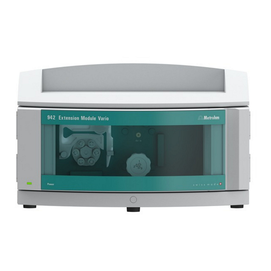
■■■■■■■■■■■■■■■■■■■■■■ 2.1 Front 2 Overview of the instrument Front Figure 1 Front Peristaltic pump (see chapter 3.4.1, page 15). (see chapter 3.6, page 28). Suppressor drive Standby indicator (see chapter 3.4.1, page 15). ■■■■■■■■ 942 Extension Module Vario SeS/PP (2.942.0500) -
Page 15: Rear
Installed between the instrument and base tray (3-B). ■ Stacked next to the instrument (3-C). In this case, we recommend ■ ordering a separate base tray (6.2061.110) and a separate bottle holder (6.2061.100) for the stack. ■■■■■■■■ 942 Extension Module Vario SeS/PP (2.942.0500) -
Page 16: Figure 3 Proposed Setup
If this is not possible, extension modules that are farther apart have to be connected together using a longer connecting cable (6.2156.070). ■■■■■■■■ 942 Extension Module Vario SeS/PP (2.942.0500) -
Page 17: Setting Up The Instrument
1 Remove all of the transport locking screws with the hex key. Store the transport locking screws in a safe place. Reinsert the transport locking screws each time you transport the instrument a significant dis- tance. ■■■■■■■■ 942 Extension Module Vario SeS/PP (2.942.0500) -
Page 18: Base Tray And Bottle Holder
To install an Extension Module under the ion chromatograph, remove the base tray and set it under the lowest instrument. 3.3.2.1 Removing/mounting the base tray Remove the base tray to install another instrument under the IC instru- ment. ■■■■■■■■ 942 Extension Module Vario SeS/PP (2.942.0500) -
Page 19: Figure 4 Removing The Base Tray
Removing the base tray 1 Tilt the instrument sideways and lay it down flat. 2 Loosen the 4 cylinder screws with the 3 mm hex key. Remove the cyl- inder screws and their washers. ■■■■■■■■ 942 Extension Module Vario SeS/PP (2.942.0500) -
Page 20: Figure 5 Mounting The Base Tray
3 Set the instrument back up on the base tray. Stack other instruments in the required order. Mount the bottle holder (6.2061.100) onto the topmost instrument on the stack (see "Mounting the bottle holder", page 13). ■■■■■■■■ 942 Extension Module Vario SeS/PP (2.942.0500) -
Page 21: Figure 6 Removing The Bottle Holder
2 Loosen the 2 cylinder screws with the 3 mm hex key and remove them. 3 Remove the bottle holder. Stack other instruments in the required order. Mount the bottle holder (6.2061.100) onto the topmost instrument on the stack. Mounting the bottle holder Prerequisite ■■■■■■■■ 942 Extension Module Vario SeS/PP (2.942.0500) -
Page 22: Figure 7 Mounting The Bottle Holder
4 Mount the drainage tubing again (see manual of the IC instrument). A longer section of silicone tubing (6.1816.020) may have to be cut to size and mounted (see also the manual for the IC instrument). ■■■■■■■■ 942 Extension Module Vario SeS/PP (2.942.0500) -
Page 23: Peristaltic Pump
6.1826.420 Pump tubing PharMed ® Ismaprene 0.51 mm For suppressor solutions. (orange/yellow), 3 stoppers Selecting the pump tubing and adapter 1 Select pump tubing suitable for the application (see table 1, page 15). ■■■■■■■■ 942 Extension Module Vario SeS/PP (2.942.0500) - Page 24 Coupling olive/UNF 10/32 (6.2744.034) ■ Pump tubing connection with locking nut and filter (6.2744.180): ■ Includes a locknut, 3 adapters and a tubing olive with filter holder. 2 × pressure screw, short (6.2744.070) ■ ■■■■■■■■ 942 Extension Module Vario SeS/PP (2.942.0500)
- Page 25 – Tighten it using the union nut. 2 Removing the tubing cartridge Press in the tubing cartridge's snap-action lever. ■ Tilt the tubing cartridge upwards. ■ Unhook the tubing cartridge from the mounting bolt. ■ ■■■■■■■■ 942 Extension Module Vario SeS/PP (2.942.0500)
- Page 26 ■ regeneration solution. Connecting capillaries for rinsing solution (as an alternative to STREAM) Accessories For this step, you need the following accessories: Aspiration capillary (6.1803.030) ■ 2 × pressure screw, short (6.2744.070) ■ ■■■■■■■■ 942 Extension Module Vario SeS/PP (2.942.0500)
- Page 27 The rotational speed of the drive ■ The contact pressure of the tubing cartridge ■ NOTICE Pieces of pump tubing are consumables. The service life of the pump tubing depends on the contact pressure, among other factors. ■■■■■■■■ 942 Extension Module Vario SeS/PP (2.942.0500)
-
Page 28: Mode Of Operation For The Peristaltic Pump
The pump tubing is clamped between the rollers (8-5) and the tub- ing cartridge (8-2). During operation, the peristaltic pump drive rotates the roller hub (8-6), so that the rollers (8-5) advance the liquid in the pump tubing. ■■■■■■■■ 942 Extension Module Vario SeS/PP (2.942.0500) -
Page 29: Metrohm Suppressor Module (Msm)
Rotor A (6.2844.000), must first be fitted into the adapter (6.2842.020), which can then be inserted into the suppressor housing. A connecting piece (6.2835.010) is used for all rotors for connecting the Metrohm Suppressor Module (MSM) to the IC system. NOTICE The instruments are supplied without rotor and without adapter. - Page 30 1 is on top and the three pins of the connecting piece fit into the corresponding recesses on the suppressor drive. 4 Attaching the union nut Tighten the union nut on the thread of the suppressor drive by hand (do not use any tools). ■■■■■■■■ 942 Extension Module Vario SeS/PP (2.942.0500)
-
Page 31: Connecting The Metrohm Suppressor Module (Msm)
3.5.2 Connecting the Metrohm Suppressor Module (MSM) The three entries and exits of the suppressor units, numbered 1, 2 and 3 on the connecting piece, each have two permanently installed PTFE capil- laries. ■■■■■■■■ 942 Extension Module Vario SeS/PP (2.942.0500) -
Page 32: Figure 9 Metrohm Suppressor Module (Msm) - Connection Capillaries
■■■■■■■■■■■■■■■■■■■■■■ 3.5 Metrohm Suppressor Module (MSM) Figure 9 Metrohm Suppressor Module (MSM) – Connection capillaries Outlet capillary for the eluent. Inlet capillary for the eluent. regenerant waste reg. Inlet capillary for the regeneration solution. Outlet capillary for the regeneration solu- tion;... - Page 33 MCS (see chapter 3.6.2, page 29). 3.5.2.2 Installing bottles with auxiliary solutions Accessories To connect the bottles of the auxiliary solutions, you will need the follow- ing accessories: Accessories from the accessory kit: IC Vario/Flex SeS (6.5000.020) ■ ■■■■■■■■ 942 Extension Module Vario SeS/PP (2.942.0500)
- Page 34 2 Connect the capillary labeled regenerant to the outlet of the pump tubing using a pressure screw (6.2744.070). 3 Connect the PTFE capillary from the regeneration solution bottle to the inlet of the pump tubing. ■■■■■■■■ 942 Extension Module Vario SeS/PP (2.942.0500)
- Page 35 ■■■■■■■■■■■■■■■■■■■■■■ 3 Installation 3.5.2.4 Connecting the rinsing solution Various possibilities exist for rinsing the Metrohm Suppressor Module: Rinsing solution via STREAM (recommended) ■ Use the eluent from the conductivity detector as rinsing solution. Rinsing solution via peristaltic pump ■ Prepare the rinsing solution in a separate bottle and convey it with the peristaltic pump.
-
Page 36: Metrohm Co Suppressor (Mcs)
CO to be diffused out of the eluent stream. The ambient air is drawn in by a CO adsorption cartridge to filter out the CO from the air. ■■■■■■■■ 942 Extension Module Vario SeS/PP (2.942.0500) -
Page 37: Connecting The Mcs
■■■■■■■■■■■■■■■■■■■■■■ 3 Installation 3.6.2 Connecting the MCS The MCS is connected between the Metrohm Suppressor Module (MSM) and the conductivity detector. Connecting the MCS Figure 10 Connecting the MCS Air aspiration capillary Pressure screw, short (6.2744.070) For drawing in air with low CO content (via Installed on the air aspiration capillary. -
Page 38: Installing Adsorption Cartridges
1 Remove the protective cap from the tip of the CO adsorption car- tridge CW. 2 Attach the dust filter to the tip of the CO adsorption cartridge CW. 3 Remove the label from the lid of the CO adsorption cartridge CW. ■■■■■■■■ 942 Extension Module Vario SeS/PP (2.942.0500) - Page 39 Installing the CO adsorption cartridge CW Accessories Adsorption cartridge holder (6.2057.080) ■ Prepared CO adsorption cartridge CW (6.2837.100) ■ CAUTION The following preparatory steps absolutely must be carried out for CO suppression to operate correctly. ■■■■■■■■ 942 Extension Module Vario SeS/PP (2.942.0500)
- Page 40 Push two clips into the slots on the adsorption cartridge holder. ■ 2 Connecting the CO adsorption cartridge CW Attach the capillary connected to the Metrohm CO Suppressor's (MCS) Air in connection to the tip of the CO adsorption cartridge...
-
Page 41: Connecting An Extension Module
Extension Module and tighten it in place. 2 Plug the other end of the connecting cable into the Extension Module connection socket on the IC instrument and tighten it in place. ■■■■■■■■ 942 Extension Module Vario SeS/PP (2.942.0500) - Page 42 (6.2156.070) into the In connection socket on the second Extension Module and tighten it in place. 2 Plug the other end of the connecting cable into the Out connection socket on the first Extension Module and tighten it in place. ■■■■■■■■ 942 Extension Module Vario SeS/PP (2.942.0500)
- Page 43 A rotor is correctly inserted. ■ The MCS is connected. ■ The 942 Extension Module Vario SeS/PP is connected to the 940 Pro- ■ fessional IC Vario. You can find additional information on carrying out initial start-up in the Start-up chapter in the manual for the IC instrument and the MagIC Net online help.
-
Page 44: Servicing The Door
The pump tubing (6.1826.xxx) is made of PVC or PP and therefore must not be used for rinsing with solutions containing organic solvents. In this case, use different pump tubing or use another pump for rinsing. ■■■■■■■■ 942 Extension Module Vario SeS/PP (2.942.0500) -
Page 45: Servicing The Peristaltic Pump
The filters may need to be replaced more frequently, depending on the application. Accessories For this step, you need the following accessories: 1 filter from the spare filter set (6.2821.130) ■ 2 adjustable wrenches (6.2621.000) ■ Tweezers ■ ■■■■■■■■ 942 Extension Module Vario SeS/PP (2.942.0500) -
Page 46: Metrohm Suppressor Module (Msm)
Therefore, always mount the inlet and outlet capillaries according to the diagram outlined in Chapter Connecting the Metrohm Suppressor Module (MSM), page 23. The Metrohm Suppressor Module (MSM) consists of three suppressor units, which, in rotation, are (1.) used for suppression, (2.) regenerated ■■■■■■■■... -
Page 47: Taking Care Of The Suppressor Housing
If the Metrohm Suppressor Module (MSM) is in a dry state, it must be rinsed for at least five minutes before it may be switched over. -
Page 48: Figure 12 Parts Of The Metrohm Suppressor Module (Msm)
■■■■■■■■■■■■■■■■■■■■■■ 5.3 Metrohm Suppressor Module (MSM) 5.3.3.1 Parts of the Metrohm Suppressor Module (MSM) The SPM is made up of the same parts as the Metrohm Suppressor Mod- ule (MSM). Figure 12 Parts of the Metrohm Suppressor Module (MSM) Union nut... - Page 49 Pump tubing made of PVC must not be used for solutions containing organic solvents. We recommend using the high-pressure pump for regeneration. Regenerating the anion suppressor rotor 1 Disconnecting the Metrohm Suppressor Module (MSM) from the IC system Disconnect the capillaries of the MSM labeled regenerant and ■...
- Page 50 As soon as all three suppressor units have been rinsed, disconnect ■ the capillary labeled rinsing solution from the coupling. 4 Connecting the Metrohm Suppressor Module (MSM) to the IC system Reconnect the capillaries of the MSM labeled regenerant and ■...
- Page 51 5.3.3.4 Cleaning the Metrohm Suppressor Module (MSM) In the following cases, it may be necessary to clean the Metrohm Suppres- sor Module (MSM): Increased backpressure at the MSM's connection tubing. ■ Irremediable blockage of the MSM (solutions can no longer be pum- ■...
- Page 52 Check whether water comes out at the connecting piece. ■ If one of the capillaries remains blocked, the connecting piece (see "Replacing parts of the Metrohm Suppressor Module (MSM)", page 46) must be replaced (order number 6.2835.010). 4 Cleaning the rotor Clean the sealing surface of the rotor (12-3) with ethanol using a ■...
- Page 53 5.3.3.5 Replacing parts of the Metrohm Suppressor Module (MSM) Parts of the Metrohm Suppressor Module (MSM) may need to be replaced in the following cases: Irremediable loss of suppressor capacity (reduced phosphate sensitivity ■...
- Page 54 ■■■■■■■■■■■■■■■■■■■■■■ 5.3 Metrohm Suppressor Module (MSM) Replacing parts of the Metrohm Suppressor Module (MSM) 1 Disconnecting the Metrohm Suppressor Module (MSM) from the IC system Switch off the instrument. ■ Disconnect all capillaries of the MSM from the IC system.
- Page 55 Reattach the union nut (12-1) and tighten by hand (do not use a ■ tool). 7 Connecting and conditioning the Metrohm Suppressor Mod- ule (MSM) Reconnect all capillaries of the MSM to the IC system. ■...
-
Page 56: Servicing The Metrohm Co Replacing The Co Adsorption Cartridge Cw
CW 1 Remove the depleted CO adsorption cartridge CW from the adsorp- tion cartridge holder. 2 Remove the Air in capillary of the Metrohm CO Suppressor (MCS). 3 Professionally dispose of the depleted CO adsorption cartridge CW. Installing the new CO... -
Page 57: Problems And Their Solutions
Check the flow of the regeneration solution high. flow of regeneration solu- and of the rinsing solution . tion or rinsing solution. MCS – The CO suppressor Connect the CO suppressor. is not connected. ■■■■■■■■ 942 Extension Module Vario SeS/PP (2.942.0500) - Page 58 37). SPM – Backpressure too Clean the SPM (see chapter 5.3.3.4, page 43) high. or replace parts (see chapter 5.3.3.5, page 45). Peristaltic pump – Pump Replace the pump tubing. tubing defective. ■■■■■■■■ 942 Extension Module Vario SeS/PP (2.942.0500)
-
Page 59: Reference Conditions
Housing Dimensions Width 365 mm Height 131 mm Depth 380 mm Material of base Polyurethane hard foam (PUR) with flame retardation for fire class tray, housing and UL94V0, CFC-free, coated bottle holder ■■■■■■■■ 942 Extension Module Vario SeS/PP (2.942.0500) -
Page 60: Weight
Fluoropolymer Resistance to sol- No restriction (except PFC) vents Vacuum Working range Microprocessor-controlled/stabilized Time to estab- < 30 s lish after start- Capillary volume 400 µL Recommended 0.1 - 1.0 mL/min flow range ■■■■■■■■ 942 Extension Module Vario SeS/PP (2.942.0500) -
Page 61: Interfaces
1 15-pin D-sub plug (male) Connection to the ion chromatograph or to another Extension Module. 1 15-pin D-sub plug (female) Connection to another Extension Module or to an 891 Professional Analog Out (optional). ■■■■■■■■ 942 Extension Module Vario SeS/PP (2.942.0500) - Page 62 The PDF file with the accessories data is created. NOTICE Once you have received your new product, we recommend download- ing the accessories list from the Internet, printing it out and keeping it together with the manual for reference purposes. ■■■■■■■■ 942 Extension Module Vario SeS/PP (2.942.0500)
- Page 63 Technical specifications ..52 Vacuum pump Pump tubing Protection ......10 Heavy metals Install ......... 15 Contamination of suppressor Service life ......36 ........... 40 Pump tubings High-pressure pump Overview ......15 Protection ......10 ■■■■■■■■ 942 Extension Module Vario SeS/PP (2.942.0500)
Need help?
Do you have a question about the 942 Extension Module Vario SeS/PP and is the answer not in the manual?
Questions and answers