Bogen NYQUIST NQ-S1810WT-G2 Installation Manual
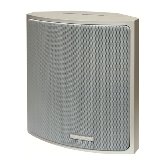
Gen-2 voip wall baffle speaker
Hide thumbs
Also See for NYQUIST NQ-S1810WT-G2:
- Configuration manual (20 pages) ,
- Configuration manual (23 pages) ,
- Configuration manual (32 pages)

Related Manuals for Bogen NYQUIST NQ-S1810WT-G2


Summary of Contents for Bogen NYQUIST NQ-S1810WT-G2
- Page 1 NQ-S1810WT-G2 Nyquist Gen-2 VoIP Wall Baffle Speaker Installation 740-00124-00B 2006 ©2020 Bogen Communications, Inc. Specifications are subject to change.
- Page 2 NQ-S1810WT-G2 Nyquist Gen-2 VoIP Wall Baffle Speaker Installation Manual With the Nyquist Series Gen-2 VoIP Wall Baffle Speaker, there is no need for external amplifiers, traditional intercom wiring, or transformer taps to manually set or adjust. Connect the speaker via Cat5 to a Power-Over-Eth- ernet (PoE) Switch or PoE Injector, and it is ready to use.
- Page 3 Speaker Layout The layout of the speakers should be planned prior to installation. Because wall baffle speakers are designed to project forward, it is best to aim them in the same direction as this provides for both greater coverage and clarity. You can use the building’s roof pillars or other available sup- ports for mounting the wall baffles.
- Page 4 Step 1 Select the mounting option from Figures 3–6 and use the appropriate hardware for gang box mount or wall mount. Bogen provides the screws and the washers for mounting on a standard electrical gang box, but when mounting directly to a wall or other surface, you must supply the appropriate hardware for the specific wall/surface construction type (for example, concrete cinder block, metal beams etc.).
- Page 5 Speaker Installation (cont’d) Corner Mount Tilt Mount Side View Figure 5 Figure 6 Step 2 When applicable, use the pluggable CAN bus connector to attach one or more NQ-E7020 Digital Call Switch to the Nyquist VoIP Full Duplex Module 820-00071-00 as shown in Figure 7. Figure 7 NQ-E7020 Digital Call Switch...
- Page 6 Speaker Installation (cont’d) Step 5 Use Category 5 or higher Ethernet cable to connect the speaker (Figure 8). The power is supplied by PoE using an 802.3af compliant network switch or PoE injector Figure 8 Step 6 To assemble the Wall Baffle Speaker (Figure 9), first align the two notches (A) located at the top of the speaker baffle with the notches (B) at the top of the rear housing.
- Page 7 Compliance NOTE: This equipment has been tested and found to comply with the limits for a Class A digital device, pursuant to Part 15 of the FCC rules. These limits are designed to provide reasonable protection against harmful interference when the equipment is operated in a commercial environment.
- Page 8 (as confirmed by Bogen upon inspection) during the warranty period will be repaired or replaced by Bogen, at Bogen’s option, with new or refur- bished product, provided the product is shipped insured and prepaid to: Bogen Factory Service Depart- ment: 4570 Shelby Air Drive, Suite 11, Memphis, TN 38118, USA.
Need help?
Do you have a question about the NYQUIST NQ-S1810WT-G2 and is the answer not in the manual?
Questions and answers