Bogen HFCS1 Installation And Use Manual
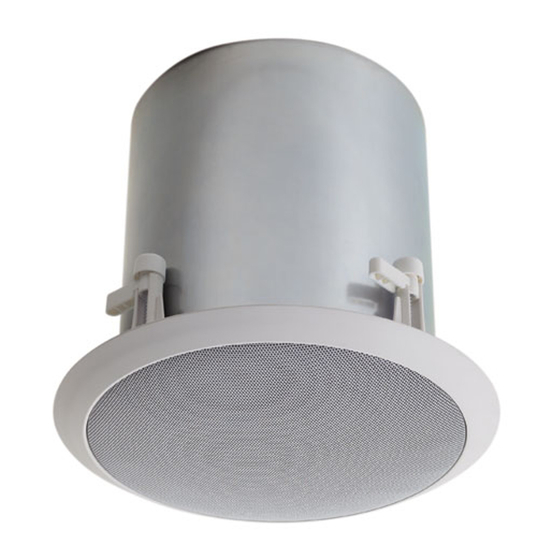
Bogen communications installation and use manual high-fidelity ceiling speaker hfcs1
Hide thumbs
Also See for HFCS1:
- Installation and use manual (9 pages) ,
- Specifications (2 pages) ,
- Wiring diagrams (4 pages)

Subscribe to Our Youtube Channel
Related Manuals for Bogen HFCS1


Summary of Contents for Bogen HFCS1
- Page 1 High-Fidelity Ceiling Speaker HFCS1 Installation and Use Manual © 2003 Bogen Communications, Inc. All rights reserved. Specifications subject to change without notice. 54-2091-01B 0406...
-
Page 2: Product Description
The HFCS1 features a removable snap-lock input connector, providing easy wire connection for input as well as loop-through to the next speaker. IMPORTANT The HFCS1 is not an outdoor speaker. Do not expose the speaker to rain or moisture.The HFCS1 should be installed by qualified personnel. -
Page 3: Product Diagrams
HFCS1 Front Drawing 1. Coaxial Driver Assembly 2. Dual Bass Tuning Vents (x2) 3. Grille Retention Groove 4. Power Tap Selection Switch 5. Mounting Clamp Screws (x4) HFCS1 Rear Drawing 6. Metal Back Can 7. Snap-Lock Input Connector 8. Mounting Clamps (x4) HFCS1 Rear Drawing 9.Terminal Covers (2 identical halves) -
Page 4: Installation
1. Begin by cutting a 10-¾" circular hole where the HFCS1 will be installed. If using a TBCR, then follow its installation instructions for the specific type of environment the HFCS1 is being installed in. -
Page 5: Speaker Wiring
All wiring should be done prior to installation and then plugged into the rear of the HFCS1. Wiring is terminated at a snap-lock input connector. There are two positive and two negative terminals to accommodate daisy- chaining of speakers in a system. - Page 6 The front-mounted selector switch is used to set the appropriate power level or impedance for your system. Using a small, flat-blade screwdriver, turn the knob until the slot points to the power level you require. 70V/100V Systems Both power setting scales for 70V and 100V systems are labeled on the speakers.
-
Page 7: Specifications
4 Terminal Snap-Lock Input Connector Minimum 11" (From front of Mounting Surface) Input Terminal Cover (2 Halves); (4) Screws; (1) Snap-Lock Input Connector Tile Bridge Support Ring (TBCR); Cable Kit (CK10) HFCS1 65 Hz to 19 kHz " PolyCone ") Polycarbonate Dome 120°... -
Page 8: Limited Warranty
CK10 is available in black, white, or silver. Limited Warranty The High Fidelity Ceiling Speaker, model HFCS1, is warranted to be free from defects in material or workmanship for three (3) years from the date of sale to the original purchas- er.
Need help?
Do you have a question about the HFCS1 and is the answer not in the manual?
Questions and answers