Bogen NQ-S1810CT-G2 Configuration Manual
Voip speaker
Hide thumbs
Also See for NQ-S1810CT-G2:
- Installation manual (12 pages) ,
- Configuration manual (20 pages) ,
- Configuration manual (32 pages)

Subscribe to Our Youtube Channel
Related Manuals for Bogen NQ-S1810CT-G2


Summary of Contents for Bogen NQ-S1810CT-G2
- Page 1 VoIP Speaker Configuration Guide NQ-S1810CT-G2, NQ-S1810WT-G2 © 2021–2022 Bogen Communications LLC All rights reserved. 740-00121B 220518...
-
Page 2: Table Of Contents
Contents Configuring the Nyquist VoIP Speakers ........1 Using the Dashboard . -
Page 3: Configuring The Nyquist Voip Speakers
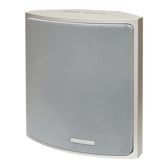
Configuring the Nyquist VoIP Speakers The Nyquist VoIP Ceiling Speaker Gen 2 (NQ-S1810CT-G2) and Nyquist VoIP Wall Baffle Speaker Gen 2 (NQ-S1811WT-G2) are VoIP talkback speakers designed to work with the Nyquist Series IP network-based intercom and paging solution. The ceiling talkback speaker assembly consists of an 8" cone speaker and VoIP module preassembled onto a 13"... -
Page 4: Using The Dashboard
Link icon. At the Nyquist Appliance Login page, enter username and password, and then select Login. The default username is admin; the default password is bogen. The dashboard for the selected appliance appears. Using the Dashboard Figure 2. - Page 5 Table 1. Appliance Dashboard Fields Device Type Identifies the model of this device. Serial Number Identifies the serial number for the device. MAC Address Identifies the Media Access Control (MAC) address, which is a unique identifier assigned to network inter- faces for communications on the physical network seg- ment.
-
Page 6: Updating Firmware
Table 2. Appliance Dashboard Buttons (Continued) Help Accesses the appliance’s online help. Manual Displays the appliance’s configuration manual. Logout Logs out of the appliance’s dashboard. Updating Firmware When you select Firmware Update from the appliance’s web UI, the Firmware Update page appears. - Page 7 Check for Updates button checks the Bogen website for the latest firmware version available. If a version newer than the one currently installed is found, it is downloaded to the appliance. If you already have a firmware file you would like to install to the appliance, select Upload Firmware to upload the firmware file from your computer to the appliance.
-
Page 8: Network Settings Tab Parameters
Table 3. Firmware Update settings Restore Factory Settings Returns the appliance to its original factory con- figuration. Note: This does not install the original appliance firmware. The firmware will not be changed. Reboot Appliance Restarts the appliance. Network Settings Tab Parameters Network settings can be configured dynamically by the Nyquist server or manually by using the appliance’s web UI. - Page 9 Figure 4. Network Settings Network settings are described in the following table: Table 4. Network Settings IP Address Identifies the IP address assigned to the appliance. Netmask Identifies the subnetwork subdivision of an IP net- work. Gateway Identifies the address, or route, for the default gate- way.
- Page 10 Table 4. Network Settings (Continued) NTP Server Identifies the IP address or the domain name of the Network Time Protocol (NTP) Server. Note: This field is only editable when Standalone Operation is enabled. TFTP Server Identifies the host name or IP address of the Trivial File Transfer Protocol (TFTP) server.
-
Page 11: Configuration Settings Tab Parameters
Table 4. Network Settings (Continued) DHCP Enabled Indicates if the device is enabled to use DHCP to retrieve its IP configuration. Reboot Appliance Indicates that this appliance should reboot when the Save button is clicked. Configuration Settings Tab Parameters The easiest way to configure Nyquist appliances is to obtain configuration settings from the Nyquist server by selecting Get Configuration From Server. - Page 12 The following table describes the Configuration Settings tab settings: Table 5. Configuration Settings (Standalone disabled) Get Configuration from Retrieves configuration settings (i.e., web username, server, and local port) from the TFTP server specified in Server the Network Settings (see "Network Settings Tab Parameters”...
-
Page 13: Standalone Operation Configuration Settings
Standalone Operation Configuration Settings Figure 6. Appliance Configuration Settings (Standalone enabled) The following table describes the Configuration Settings tab settings when Standalone Operation is enabled for this device: Table 6. Configuration Settings (Standalone enabled) Device Type Displays the type of this device. Device Name Provides a name for this device. - Page 14 Table 6. Configuration Settings (Standalone enabled) Web Confirm Password Re-enter the password used to log into the appliance. Time Zone Specifies the time zone in which the device resides. Output Power (Watts) Specifies the output power for the amplifier in Watts. Valid values are: 1/8, 1/4, 1/2, 1, 2, and 4.
- Page 15 Multicast IP Address Specifies the multicast IP address on which to receive audio streams. Multicast Port Number Specifies the multicast port on which to receive audio streams. Codec Specifies the codec to be used when decoding audio. Select one of the following values: •...
- Page 16 Channels Channel(s) on which the audio streams will be output. One or more of the following values: • Speaker Tip: Fine tuning of levels per output channel can be adjusted using DSP settings. Cut Level (dB) Specifies the cut level for the audio stream. This can be a value from -70 to 0 dB.
-
Page 17: Setting Dsp Parameters
Setting DSP Parameters When you select DSP from the appliance’s web UI, the DSP page appears. Figure 7. DSP Page From this page, you can set parameters for DSP, which is a form of processing that uses digital data to simulate characteristics found in analog circuits. With DSP, you can alter analog signals, such as audio signals, that have been converted to a digital format. -
Page 18: Setting The Channel Level
Table 7. DSP Features Intercom Tuning Allows you to specify settings used in intercom calls. Presets Allows you to use preset DSP settings for the selected speaker type. Setting the Channel Level The Channel Level control is a vertical slider that is adjusted in 1-dB increments and con- trols the output level for the channel. -
Page 19: Intercom Tuning
Intercom Tuning Selecting Intercom Tuning from the Menu icon on the DSP page displays the Intercom Tuning page. Figure 8. Intercom Tuning Settings The Intercom Tuning page has level indicators for input and output signals and contains the following settings (see Table 8). -
Page 20: Presets
(e.g., microphone placement), these DSP settings must be customized for each model. Bogen has created predefined sets of model-specific DSP configurations to customize the signal for each device. These configurations are available via Presets. Note: It is important that the preset corresponding to the speaker model be specified. - Page 21 Figure 9. Presets Settings The Presets page allows you to select the Speaker Type. Table 9. Preset Settings Speaker Type Select a predefined Preset configuration from the list of speaker models. Available options are: • NQ-S1810CT (ceiling-mounted speaker) • NQ-S1810WT (wall-mounted speaker)
-
Page 22: Accessing Log Files
Accessing Log Files A log file records events and messages that occur when software runs, to be used when troubleshooting the appliance. From the appliance’s web-based UI, log files can be viewed directly or exported via download to your PC, Mac, or Android device, where they can be copied to removable media or attached to an email for technical support. - Page 23 Available logs are described in the following table. If a log file is empty, however, it will not appear in the drop-down list of available logs. Table 10. Logs Description ampws.log Contains information about protection status and logs protection events with temperature information at the time of event.
Need help?
Do you have a question about the NQ-S1810CT-G2 and is the answer not in the manual?
Questions and answers