Advertisement
Quick Links
APPLICATION
Jeep Wrangler Unlimited (JK)
(4-Door Only)
AMP RESEARCH TECH SUPPORT 1-888-983-2204 (Press 2) Monday - Friday, 7:00 AM - 5:00 PM
Designed and manufactured by AMP Research. Patent 6,830,257 / 6,641,158 / 6,834,875 / 6,938,909 / 6,942,233 / 7,007,961 Other US and worldwide
patents pending. Three-year limited warranty. Professional installation is recommended. Nationally Distributed by Bestop.
www.amp-research.com
I N S T A L L A T I O N G U I D E
2007–2017
1/8
AMP Part #
78122-01A
INSTALLATION TIME
3-5 Hours
Professional installation recommended
SKILL LEVEL
2
1
4= Experienced
TOOLS REQUIRED
q 13 mm socket
q 13 mm end wrench
q Ratchet wrench and extension
q Wire crimpers
q Wire stripper/cutter
q 3/16" hex key wrench (allen wrench )
q 4 mm hex key wrench (allen wrench )
q 5 mm hex key wrench (allen wrench )
WARRANTY
5-Year Limited Warranty
IM78122 rev 01.02.20
4
3
Advertisement

Related Manuals for AMP Research PowerStep XTreme 78122-01A


Summary of Contents for AMP Research PowerStep XTreme 78122-01A
- Page 1 AMP RESEARCH TECH SUPPORT 1-888-983-2204 (Press 2) Monday - Friday, 7:00 AM - 5:00 PM Designed and manufactured by AMP Research. Patent 6,830,257 / 6,641,158 / 6,834,875 / 6,938,909 / 6,942,233 / 7,007,961 Other US and worldwide patents pending. Three-year limited warranty. Professional installation is recommended. Nationally Distributed by Bestop.
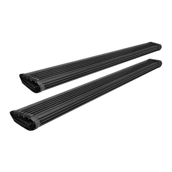
- Page 2 PARTS LIST AND HARDWARE IDENTIFICATION End cap left (x1) End cap right (x1) T-nut insert (x2) Socket cap screw (x2) Nut plate (x2) Step assembly Adaptor Motor Linkage Motor Linkage Passenger (2 door) Driver (2 door) Wire Harness Motor Motor Cover Controller www.amp-research.com IM78122 rev 01.02.20...
- Page 3 PARTS LIST AND HARDWARE IDENTIFICATION Socket Cap Screw Button Head Bolt U nut Hex Flange Bolt Washer Black Flat Head Cap Screw Posi-Taps™ (Red/Grey) Cinch Fastener Cable Tie 6” Cable Tie 11” LED Lamp Shim Light bracket Butt Connector Flange Head Bolt www.amp-research.com IM78122 rev 01.02.20...
- Page 4 Locate rear linkage installation position Install adaptor as shown in front of rear body mount Hole not used Torque to Front of vehicle 16 ft-lbs. (22 Nm) Passenger side shown above Install Rear Drive linkage Note: Install light Hole is not present in pinch weld. bracket between Hole can be drilled if desired using pinch weld and...
- Page 5 Mount step extrusion to linkage assemblies. Line up Line up rear of step extrusion with rear fender well. t-nuts in step assembly with slots in lower mounts of linkage assemblies. Fasten loosely to allow for adjustments. Tighten 4 socket cap screws with 3/16” allen wrench. Remove fuse from Power Step wire harness.
- Page 6 Remove passenger side front door sill. Lift carpet. Slit rubber grommet and pass trigger wires through grommet in floor into passenger compartment. Use Posi-Tap connectors to connect Power Step trigger Posi-Tap™ instructions wires to like colored wires in the factory system as shown: Violet/White wire in loom coming from front door, Violet/ Yellow and Violet/Grey in main loom in door sill.
- Page 7 Remove driver side door sill and pull up carpet. Route Violet wire under carpet to driver side door sill and connect to violet wire coming from door as shown. Note: For door removal attach posi tap on chassis side of door harness. Insert plug from wire harness onto motor.s Slide Insert plastic push pin rivets in mounting holes of motor cover.
-
Page 8: Final System Check
Reinstall Fuse. Check that all doors activate the Power Step and the LED Lights work when Due to Variances in the sheet doors open and close. Reinstall any remaining trim panels. metal a shim kit is provided if Steps do not retract properly. See Step 3 for shim placement. -
Page 9: Year Limited Warranty
5-YEAR LIMITED WARRANTY AMP RESEARCH warrants this product to be free from defects in material and workmanship for FIVE (5) YEARS FROM DATE OF PURCHASE, provided there has been normal use and proper maintenance. This warranty applies to the original purchaser only.
Need help?
Do you have a question about the PowerStep XTreme 78122-01A and is the answer not in the manual?
Questions and answers