Sign In
Upload
Manuals
Brands
NTI Manuals
Measuring Instruments
ENVIROMUX E-5D
NTI ENVIROMUX E-5D Manuals
Manuals and User Guides for NTI ENVIROMUX E-5D. We have
3
NTI ENVIROMUX E-5D manuals available for free PDF download: Installation And Operation Manual, Manual
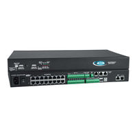
NTI ENVIROMUX E-5D Installation And Operation Manual (150 pages)
Enterprise Environment Monitoring System
Brand:
NTI
| Category:
Measuring Instruments
| Size: 10 MB
Table of Contents
Table of Contents
4
Introduction
10
Materials
12
Supported Web Browsers
13
Features and Functions
14
Installation
16
Mounting Instructions-16D
16
Figure 1- Secure Rack Mount Ears to E-16D
16
Figure 2- Mount ENVIROMUX in a Rack
16
Mounting Instructions-5D / -2D
17
Figure 3- Rotate the Tabs for Zero-RU Mounting
17
Figure 4- Mount E-5D/2D in a Rack
17
DIN Rail Mounting
18
Figure 5- Mount E-5D/2D to DIN Rail- Plastic Clip
18
Figure 6- DIN Rail Mount with Metal Clip
18
Figure 7- Sensors Connected by Cables with RJ45 Connectors
19
Figure 8- Contact Sensor Wired to RJ45 Socket
19
RJ45 Sensor Ports
19
Sensor Attachment
19
Digital in Terminals
20
Figure 9- DIGITAL in Terminal Connections
20
Liquid Detection Sensors
20
Figure 10- Secure Liquid Detection Sensor with Tape
21
Figure 11- Portion of Water Sensor Configuration Page
21
Alarm(Beacon/Siren) Connections
22
Figure 12- Connect Visual and Audible External Indicators
22
Connect Output Devices
23
Figure 13- Install Additional Devices to Output Terminals
23
Terminal Connection for RS232
24
Figure 14- Connect a Terminal for Direct RS232 Serial Communication
24
Figure 15- Connect a Terminal Using USB Console Port
24
Ethernet Connection for Remote User Control
25
Figure 16- Connect ENVIROMUX to the Ethernet
25
Modem Connection
26
USB GSM Modem
26
Figure 17- Install USB GSM Modem
26
SMS Relay Via SNMP
27
Serial GSM Modem
28
Power Connection-E-16D
29
Dual Power Option
29
Figure 18- Connect the Power Cord
29
Figure 19- Power Connections for ENVIROMUX with Dual Power Option
29
DC Power Option
30
Power Connection- E-5D/-2D
30
Figure 20- 48VDC Power Option Connections
30
Figure 21- Connect the AC Adapter and Power-Up
30
Figure 22- Power Connections on E-5D-48VDP
31
Figure 23- Power Supply Sensors-Summary Page
31
Figure 24- Connect Serially Controlled Device
32
Figure 25- Create User "Rs232
32
Remote RS232 Device Control
32
Figure 26- Connection to Serial Device Successful
33
Overview - Use and Operation
34
Sensors
34
IP Assignment
34
User Management
34
Alerts
34
Data and Event Logging
35
Email
35
Syslog
35
Snmp
35
SNMP Sensors
35
Modbus TCP/IP Support
35
External Modem
35
Power-On/Reset Operation
35
Out-Of-Box Operation
36
Expandability
36
Device Discovery Tool
37
How to Use the Device Discovery Tool
37
Figure 27- Device Discovery Tool
37
Use and Operation Via Web Interface
38
Log in and Enter Password
38
Figure 28- Login Prompt to Access Web Interface
38
Monitoring
39
Figure 29- Summary Page
39
Figure 30- Summary Page
40
Summary Page
40
Figure 31- Power Supply Status- Dual Power Model
41
Figure 32- Power Supply Alerts Configuration-Part 1
41
Power Supplies
41
Power Supply Alert Configuration
41
Figure 33- Power Supply Alerts Configuration-Part 2
42
Alarm Summary
44
Figure 34- Alarm Summary Page
44
Figure 35- Internal Sensor Configuration
45
Internal Sensors
45
External Sensors
46
Figure 36- External Sensor Reading
47
Figure 37- Sensor Configuration Page (1)
48
Figure 38- Sensor Configuration Page (2)
49
Figure 39- Sensor Configuration Page (3)
50
External Sensor Configuration
51
Figure 40- Sensor Configuration Page (4)
51
Figure 41- Chart to Setup Alert Notification
53
Figure 42- Current Sensor Added to ENVIROMUX
55
Figure 43- Configuration of Sensor Connected to E-S420MA-24V
55
Specialized Sensors (for E-S420MA-24V Current Sensor Configuration Only)
55
Contact Sensors
57
Figure 44- List of Sensors
57
Figure 45- Add a Contact Sensor
57
Figure 46- Contact Sensor Configuration Page
58
Figure 47- Contact and Digital Alert Settings
59
Figure 48- Digital Input Sensors
60
Figure 49- Select Connector on ENVIROMUX
60
Figure 50- Configure New Sensor
61
Figure 51- Status of Digital Input #2
61
Figure 52- Open Configuration from Digital Input Page
61
Figure 53- Connection that Supports Tachometer Sensor
62
Figure 54- Monitoring Output Relays
63
Figure 55- Output Relay Status
63
Figure 56- Output Relay Contact State
63
Monitor Output Relay
63
Figure 57- Configure Output Relay
64
Figure 58- IP Devices Monitored
65
Figure 59- Add New IP Device
65
IP Devices
65
Figure 60- IP Device Configuration
66
Figure 61- IP Device Configuration-More
67
Figure 62- Add IP Sensor
69
Figure 63- IP Sensor List
69
IP Sensors
69
Figure 64- SNMP Sensor Status on Summary Page
70
Figure 65- SNMP Sensor Page
70
SNMP Sensors
70
Figure 66- SNMP Sensor Configuration Page
71
Figure 67- Events Page under Smart Alerts
72
Figure 68- Event Settings for SNMP Sensor Being Monitored
72
Figure 69- Monitoring IP Cameras
73
IP Cameras
73
Figure 70- IP Camera Configuration
74
Administration
75
System Configuration
75
Figure 71- System Configuration Page
75
Figure 72- Configuration Backup and Restore
76
Figure 73- Select What will be Displayed on Connected USB LCD Monitor
77
Figure 74- Configure the Purpose of the "RS232 AUX" Port
77
Figure 75- System Configuration-Continued
78
Figure 76- Disable External Sensor Graph
79
Figure 77- Disable/Enable Relay Interlock
79
Administration-Enterprise Setup
80
Figure 78- Enterprise Configuration Page
80
Figure 79- GSM Modem Status
81
Figure 80- GSM Modem Error Alert Configuration
81
Figure 81- Example of Plain Text SMS Test Message
82
Figure 82- SMS Relay Configuration
82
Administration-Network Setup
83
Figure 83- Network Configuration Page
83
Figure 84- Apply Ipv4 or Ipv6 Settings
83
Figure 85- Configure SMTP, SNMP, and Security Settings
84
Figure 86- Configure 3G Data Connection
85
Figure 87- DDNS Settings
87
Figure 88- How to Setup SNMP to Control Output Relays
88
Figure 89- XOAUTH- Generate Verification URL
89
Figure 90- XOAUTH- Copy Verification URL
89
Figure 91- XOAUTH- Accept Prompt to Manage Your Mail
90
Figure 92- XOAUTH- Enter Verification Token
90
User Configuration
91
Figure 93- Usernames List and Status
91
Figure 94- Edit User Profile for Root User
91
Figure 95- more User Settings
92
Figure 96- more User Settings
93
Figure 97- more User Settings
94
Figure 98-Summary Page for User Without Admin Privileges
95
Group Names
96
Figure 99- Enter Custom Group Names
96
Security
97
Figure 100- Security Configuration Page
97
Using a RADIUS Server
99
Figure 101- Dictionary File of RADIUS Server
99
Figure 102- Security Configuration-X509 Certificate
101
Figure 103- Security Configuration- IP Filtering Rules
102
System Information
103
Figure 104- System Information Page
103
Administration- Firmware
104
Figure 105- Update Firmware Page
104
Advanced-Cascade Configuration
105
Figure 106- Cascade Configuration Options
105
Figure 107- Master with Local (RS485) Slaves
106
Figure 108- Cascade Configuration with Ethernet Slaves
106
Figure 109- Configure Which Slaves will be Connected to the Master
107
Figure 110- Apply Alert Settings to Alert for Slave Connection Loss
107
Figure 111- Portion of Summary Page from a Master with a Slave
109
Reboot the System
110
Figure 112- Reboot System Page
110
Figure 113- System Is Rebooting
110
Smart Alerts
111
Figure 114- Events Used for Smart Alerts
111
Figure 115- Sensor to be Used for a Predefined Event
111
Figure 116- Configuration Options for New Event
112
Figure 117- Event Configuration Options Continued
114
Figure 118- Smart Alert Summary Page
115
Figure 119- Smart Alert Configuration
115
Figure 120- Smart Alert Configuration- Continued
116
Figure 121- Smart Alert Configuration- Continued
117
Figure 122- Smart Alert Configuration- Continued
118
Figure 123- Event Logical Function Diagram
119
Figure 124- Examples of Smart Alert Conditions
120
Log
121
View Event Log
121
Figure 125- Event Log Page
121
View Data Log
122
Figure 126- Data Log Page
122
View USB Data Log
123
View USB Images
123
Figure 127- View Saved USB Data Log
123
Log Settings
124
Figure 128- View Images Saved on USB Flash Drive
124
Figure 129- Log Settings Page
125
Figure 130- Mount a USB Flash Drive
126
Figure 131- Steps to Unmount a Flashdrive
126
Support
127
Logout
127
Figure 132- Support
127
Figure 133- Logout
127
Front Panel Controls and LED Indicators
128
System Reset Button
128
Figure 134- Front Panel
128
Alarm Test/Silence Button
129
Restore Defaults Button
129
Battery Backup
129
Figure 135- USB Flash Drive/Modem/Lcd Monitor Port
130
USB Port
130
Serial Control
130
Figure 136- Mobile Login Page
131
Figure 137- Mobile Summary Page
131
Mobile Summary Page
131
E-16D Specifications
132
Front Panel Interface
132
RJ45 Sensor Inputs
132
Digital Inputs
132
Output Relays
132
Beacon Port & Siren Port
132
USB Device Ports
133
Control Serial Port "RS232
133
USB-Serial Port "Console
133
Auxiliary Power Port
133
Ethernet Port
133
Back-Up Battery
133
General Specifications
133
Tcp/Ip
133
E-5D Specifications
134
User Interface
134
RJ45 Sensor Inputs
134
Digital Inputs
134
Output Relays
134
Alarm Port
134
USB Device Ports
134
USB-Serial Port "Console
135
Auxiliary Power Port
135
Ethernet Port
135
General Specifications
135
Tcp/Ip
135
Optional Battery
135
E-2D Specifications
136
User Interface
136
RJ45 Sensor Inputs
136
Digital Inputs
136
Output Relays
136
USB Device Ports
136
USB-Serial Port "Console
136
Auxiliary Power Port
137
Ethernet Port
137
General Specifications
137
Tcp/Ip
137
Optional Battery
137
Port Assignments
138
DDNS Provider List
138
Wiring Methods
139
RS485 Sensor Cable
139
Contact Sensor Wiring
139
Troubleshooting
140
Date/Time Battery Replacement
143
E-16D Backup Battery Replacement
146
Recycling Information
147
RS485 Sensors
148
Index
149
Warranty Information
150
Advertisement
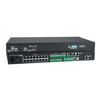
NTI ENVIROMUX E-5D Manual (59 pages)
Enterprise Environment Monitoring System
Brand:
NTI
| Category:
Measuring Instruments
| Size: 3 MB
Table of Contents
Table of Contents
3
Introduction
6
Hardware Connection
6
Terminal Connection
6
Figure 1- Connect a Terminal for Direct RS232 Serial Communication
6
Ethernet Connection
7
Figure 2- Connect a Terminal Using USB Console Port
7
Figure 3- Connect ENVIROMUX to the Ethernet
7
USB Console Port
8
Installing Drivers
8
Figure 4- Connect Terminal to USB Console Port
8
Installing an Unsigned Driver in Windows 8 and 10 (X64)
13
Software Connection
14
Connect to ENVIROMUX from a Terminal Program
14
Figure 5- Text Menu Login Screen
14
Connect to ENVIROMUX from Command Line
15
Connect Via Telnet
15
Connect Via SSH
15
Figure 6- Text Menu- Administrator Main Menu
15
Figure 7- Text Menu- User Main Menu
16
Using the Text Menu
17
Monitoring
17
Figure 8- Text Menu-Monitoring Menu
17
Figure 9- Text Menu-Sensor Status
18
Figure 10- Text Menu- Digital Input Status
18
Figure 11- Text Menu-View IP Devices
19
Figure 12- Text Menu- View Output Relay Status
19
Figure 13- Text Menu-View Remote Digital Inputs
20
Figure 14- Text Menu-View Remote Output Relays
20
Figure 15- Text Menu-View Power Supply Status
21
Figure 16- Text Menu-Configure Sensors List
22
Figure 17- Text Menu-Configuration Menu for Sensor
22
Figure 18- Text Menu-Sensor Settings
23
Figure 19- Text Menu-Non-Critical and Critical Alert Settings
24
Figure 20- Text Menu-Sensor Data Logging
25
Figure 21- Configure Digital Input Sensors
25
Figure 22- Digital Input Sensor Settings Menu
26
Figure 23- Digital Input Alert Settings
26
Figure 24- Data Logging for Digital Input Sensors
27
Figure 25- Text Menu-Configure IP Devices List
28
Figure 26- Text Menu-Configuration Menu for IP Devices
28
Figure 27-Text Menu-IP Device Settings
29
Figure 28- Text Menu-IP Device Alert Settings
30
Figure 29- Text Menu-IP Device Data Logging
31
Figure 30- Text Menu- Select Configure Output Relay
31
Figure 31- Text Menu- Output Relay Settings
32
Figure 32- Text Menu- Output Relay Alert Settings
32
Figure 33- Text Menu- IP Camera List for Configuration
33
Figure 34- Text Menu- IP Camera Settings
33
Configure Remote Digital Inputs and Output Relays
34
Figure 35- Text Menu-Configure Remote Digital Inputs and Output Relays
34
System Configuration
35
Figure 36- Text Menu- System Configuration
35
Figure 37- Text Menu-Time Settings Menu
35
Figure 38- Text Menu-Restore Default Settings
36
Enterprise Configuration
37
Network Configuration
37
Figure 39- Text Menu-Enterprise Configuration
37
Figure 40- Text Menu-Network Configuration
37
Figure 41- Text Menu-Ipv4 Settings Menu
38
Figure 42- Text Menu-Ipv6 Settings Menu
38
Figure 43- Text Menu-SMTP Server Settings
39
Figure 44- Text Menu-SNMP Server Settings
39
Figure 45- Text Menu-Misc. Service Settings Menu
40
Figure 46- Text Menu-3G Data Connect Settings
41
Figure 47- Text Menu-VLAN Settings
42
User Configuration
43
Figure 48- Text Menu-User Configuration
43
Figure 49- Text Menu-Confirm to Add New User
43
Figure 50- Text Menu-Configuration List for User
44
Figure 51- Text Menu-User Account Settings
44
Figure 52- Text Menu-User Contact Settings
45
Figure 53- Text Menu-User Activity Schedule
46
Figure 54-Text Menu- SNMP User Settings
46
Security Configuration
47
Figure 55- Text Menu-Security Configuration
47
Figure 56- Text Menu-Authentication Settings
48
Figure 57- Text Menu-IP Filtering
49
Figure 58- Text Menu-Configure IP Filter Rule
49
Event and Data Logs
51
Figure 59- Text Menu-Event & Data Logs
51
Figure 60- Text Menu-View Event Log
51
Figure 61- Text Menu-View Data Log
52
Figure 62- Text Menu-Event Log Settings
53
Figure 63-Text Menu-Data Log Settings
53
System Information
54
Reboot
54
Figure 64-Text Menu-System Information
54
Figure 65- Text Menu-Reboot the ENVIROMUX
54
Text Menu for Non-Administrative Users
55
Monitoring
55
Figure 66- Text Menu-User Main Menu
55
Figure 67-Text Menu-User Monitoring Menu
55
Figure 68- Text Menu-User Accessible Status Menus
56
User Accessible Settings
57
Figure 69- Text Menu-User Accessible Settings
57
Figure 70- Text Menu-User Account Settings
57
Figure 71- Text Menu-User Contact Settings
58
Figure 72- Text Menu-User Activity Schedule
59
Figure 73- Text Menu-User SNMP Settings
59
NTI ENVIROMUX E-5D Manual (4 pages)
RESTORE DEFAULTS VIA RS232
Brand:
NTI
| Category:
Measuring Instruments
| Size: 0 MB
Table of Contents
E-XD: RESTORE DEFAULTS VIA RS232
1
Using the Terminal Connected to the ENVIROMUX
2
Restoring the Default Configuration of the ENVIROMUX
3
Accessing the ENVIROMUX Using the Device Discovery Tool
4
Advertisement
Advertisement
Related Products
NTI ENVIROMUX-5D
NTI ENVIROMUX-2D
NTI ENVIROMUX-MINI-LXO
NTI ENVIROMUX-5DB
NTI ENVIROMUX E-16D
NTI ENVIROMUX E-MICRO-TRH
NTI ENVIROMUX E-MICRO-TRHP
NTI E-STSM-E7
NTI E-PLSD
NTI E-STHS-LCDW
NTI Categories
Extender
Boiler
Switch
Media Converter
Cables and connectors
More NTI Manuals
Login
Sign In
OR
Sign in with Facebook
Sign in with Google
Upload manual
Upload from disk
Upload from URL