
Related Manuals for SST Automation GT200-PN-RS


Summary of Contents for SST Automation GT200-PN-RS
- Page 1 Universal Serial/PROFINET IO Gateway GT200-PN-RS User Manual V 1.0 REV A SST Automation E-mail: SUPPORT@SSTCOMM.COM WWW.SSTCOMM.COM...
-
Page 2: Table Of Contents
Catalog 1 Product Overview................................4 1.1 Product Function..............................4 1.2 Product Features..............................4 1.3 Technical Specification............................4 1.4 Related Products..............................6 1.5 Revision History..............................6 2 Hardware Descriptions..............................7 2.1 Product Appearance...............................7 2.2Indicators................................7 2.3 Interface.................................8 2.3.1 Power Interface............................8 2.3.2 Serial I-RS232............................8 2.3.3 Serial II-RS485............................9 2.3.4 Standard RS485 Characteristics.........................9 2.3.5 Ethernet Interface............................. - Page 3 4.6.2 Save Configuration Project........................51 4.7 Export EXCEL..............................51 5 Installation..................................52 51 Machine Dimension............................. 52 5.2 Installation Method............................. 52 WWW.SSTCOMM.COM...
-
Page 4: Product Overview
SST-TS-CFG without complex programming and implement the communication in a short time. 1.3 Technical Specification [1] At PROFINET side GT200-PN-RS is PROFINET slave and acts as Modbus master or Modbus slave at serial side; [2] Supports standard PROFINET I/O protocol;... - Page 5 Output 001 byte Output 002 bytes Output 004 bytes Output 008 bytes Output 016 bytes Output 032 bytes Output 064 bytes Output 128 bytes Input / Output 001 byte Input / Output 002 bytes ...
-
Page 6: Related Products
can configure up to 4 nodes. [9] Modbus slave: Function code: 03H, 04H, 06H and 10H; Format: RTU and ASCII [10] Power supply: 24VDC (11V~30V); [11] Operation temp: -4℉~140℉(-20℃~60℃), Humidity: 5%~ 95% (non-condensing); [12] Built-in electrostatic protection: 15 KV ESD; Communication interface isolation: 3KV; [13] External dimensions (W*H*D): 1.57 in*4.92 in *4.33 in (40mm*125mm*110mm);... -
Page 7: Hardware Descriptions
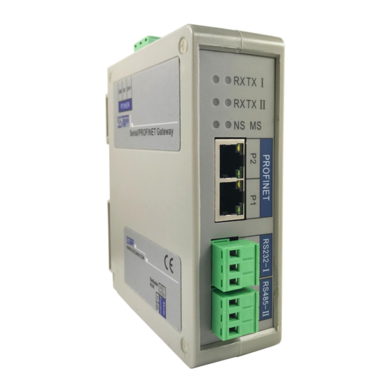
2 Hardware Descriptions 2.1 Product Appearance 24VDC Interface Serial I RX Indicator SerialⅠTX Indicator SerialⅡRX Indicator SerialⅡTX Indicator Network Indicator Module Indicator Dual PROFINET Ports SubnetⅠ Subnet Ⅱ DIP Switch Note: This picture is for reference only. Product appearance should refer to the real object. 2.2Indicators Indicators State... -
Page 8: Interface
Green Blinking Serial port data receiving SerialⅡRX No data is receiving See below table See below table Module indicator and network indicator: Module indicator state MS Network indicator state NS Description Red blinking Start-up state, waiting to initialize Initialize complete, no connection with Green on Red blinking Green on... -
Page 9: Serial Ii-Rs485
Function TXD, RS-232 data sending, Connect RXD of user device RXD, RS-232 data receiving, Connect TXD of user device 2.3.3 Serial II-RS485 Function D+, RS485 Data Positive, connect Data Positive of user device D-, RS485 Data Negative, connect Data Negative of user device 2.3.4 Standard RS485 Characteristics The basic characteristics of RS485 transmission technology: Network topology: Linear bus, there are active bus terminal resistors at both sides. -
Page 10: Ethernet Interface
on the panel. 2.3.5 Ethernet Interface Ethernet interface uses RJ-45 plug-in; its pin (standard Ethernet signal) is defined as below: Signal Description TXD+, Tranceive Data+, Output TXD-, Tranceive Data-, Output RXD+, Receive Data+, Input Bi-directional Data+ Bi-directional Data- RXD-, Receive Data- Bi-directional Data+ Bi-directional Data- WWW.SSTCOMM.COM... -
Page 11: Quick Start Guide
NS green on, MS green on. Notes: How to find out how many GT200-PN-RS devices are in the LAN, including MAC address, IP address and name of devices. Users can see chapter 3.4 Change Device IP and Name for help. - Page 12 protocol parameters. Also, users can choose to conduct the conflict detection to memory mapping data of the gateway. After installation, double click the software icon to enter into the main interface of the software: See chapter 4 for the detailed using method of the gateway configuration software SST-TS-CFG. WWW.SSTCOMM.COM...
-
Page 13: Run
The data conversion between PROFINET network and serial of GT200-PN-RS is established by "mapping". GT200-PN-RS has two data buffers, one is input buffer (1K bytes) with address range 0x0000-0x03FF; the other is output buffer (1K bytes) with address range 0x4000-0x43FF. - Page 14 0x0000-0x03FF and 0x4000-0x43FF and send data to the serial slave device. When serial slave devices didn't give any response (if they did), if there exists data in response, GT200-PN-RS will write them to the address range of 0x0000-0x03FF. The specific data size will depend on users' configuration.
- Page 15 The Master protocol works in Change of Value output mode and is executed as follows: 1. If command N is read, execute command N. Otherwise, check whether the memory mapping data contained in the request frame of command N is changed. If there is a change, execute the command N. 2.
- Page 16 Four-byte register swap is 2 registers for unit exchange, and the exchange mode is shown in the following table: Before exchange After exchange Byte index Byte value Byte index Byte value 0x12 0x56 0x34 0x78 0x56 0x12 0x78 0x34 Four-Byte Big-endian and Little-endian Swap ...
- Page 17 to the buffer After adding byte swap processing: 1. Read a certain length of data from the buffer (input or output), byte swap processing, then put it in the frame buffer of the command, and finally send the command 2. When the command has a response, the data is separated from the response frame of the command ,byte swap processing, then copied to the buffer Note: When the byte swapping process is performed, the data to be processed is divided according to a specific length.
-
Page 18: Self-Defined Protocol
GT200-PN-RS.Our "clear or hold" is for this mapped data area. Specifically, if "clear" is selected, all data in the map area will be set to 0 after the response timeout; if " hold", the content of the map data area will not be changed after the response timeout. - Page 19 [High byte of input data start address] [Low byte of input data start address] [Output data 1]…… [Output data n] [Parity] Notes: Output means the data that users device writes to GT200-PN-RS, input means the data that users device gets from GT200-PN-RS.
-
Page 20: User Config
3.3.3 User Config 3.3.3.1 Definition Common mode protocol message of GT200-PN-RS can be set freely by users, which solves the communication problem between Modbus standard protocol and Modbus nonstandard protocol devices. There are two operation modes under common mode: POLL and READ. Working principle of POLL is similar with Modbus communication protocol, which uses request and response communication way and every subnet can set 30 commands under common mode;... - Page 21 End of Frame: HEX input, max bytes number: 3 Send order in RTU format: header, data, constant, parity and end Receive order in RTU format: header, data, constant, parity and end Send order in ASCII format: header, constant, data, parity and end Receive order in ASCII format: header, constant, data, parity and end For example, configuring Modbus commands, RTU transmission format: Request:...
- Page 22 Notes: Under RTU transmission format, supports following parity: None, CRC check and sum check For example, configuring Modbus command, ASCII transmission format: : (3A) Slave Function Number of data Data 1 …… Data n LRC high byte LRC low byte CR (0D) LF (0A) Command configuration example is as below:...
- Page 23 Notes: Under ASCII transmission format, supports parity: None, LRC check and sum check Note: User Config-POLL in different "communication mode", the frame format is different!!\ RTU frame: header+ data+constant+parity +end ASCII frame:header+constant(ASCII)+data(ASCII)+parity(ASCII) +end 3.3.3.3 User Config-Receiving only User Config-Receiving only mode only receives data and doesn't respond. It can be used in receiving data of bar code scanner devices.
- Page 24 “Check Mode”: There are three checking method: no parity check, CRC check, and sum check. Note that when the GT200-PN-RS transmits data to the PN side, the field will automatically lose the check value according to the check mode. For example, one byte of the end of the frame is discarded when the sum check is performed, and two bytes of the end of the frame are discarded when the CRC check is performed.
-
Page 25: Change Device Ip And Name
3.4 Change Device IP and Name 3.4.1 Scan Devices on LAN 1. Open SST-TS-CFG and click Tools on the menu bar, shown as below: 2. Click "Assign Ethernet Parameters" will pop up below interface: WWW.SSTCOMM.COM... -
Page 26: Change Ip Info And Name
3. Click "Scan", the dialog box will be shown as below: You can see that GT200-PN-RS device is on the LAN, showing its "IP", "MAC address", "Device Name", "Gateway" and "Subnet". 3.4.2 Change IP Info and Name 1. Scan the device according to chapter 3.4.1 and log in the device, the interface is shown as below... - Page 27 You can see that after log in the device "Target MAC address" shows MAC address of GT200-PN-RS (unmodified). 2. Modify IP address to "192.168.0.188", gateway address to "192.168.0.1" and click "Assign Ethernet Parameters", its operation interface is shown as below: If modification is successful, it will pop up the dialog box below: WWW.SSTCOMM.COM...
- Page 28 Click "OK". 3. Change device name to "gt200pnrs" and click "Assign ", shown as below: If successful, it will pop up the dialog box as below: Click "OK". 4. Click again "Scan" will lead to scanning device again. See below: WWW.SSTCOMM.COM...
-
Page 29: Ip Address Conflict Resolution
GT200-PN-RS devices. If there exits confliction of IP address and device name, users can change IP address and name of GT200-PN-RS according to chapter "3.4 Change IP Info and Name" and ensure that others IP address and name are different (Notes: after changing is complete, some relevant change should be taken in PLC modeling and users must ensure the IP address and name of GT200-PN-RS is the same with that of PLC modeling). - Page 30 You can see the IP address is reset to "0.0.0.0", choose the device and log in, the dialog box is shown as below: Set "IP", "Subnet" and "Gateway" to "192.168.0.188", "255.255.255.0" and "192.168.0.1" and you will see the below picture: WWW.SSTCOMM.COM...
-
Page 31: Restore To Default Configuration
Sometimes it will appear the phenomenon of configuration failure. When that condition happens, the network LED is off, module LED red blinking (the same instruction as system startup). Now, you can't scan GT200-PN-RS through SST-TS-CFG until restoring to the default configuration. -
Page 32: Software Instructions
Double click software icon to enter the main interface of software: 4.1 User Interface The interface of GT200-PN-RS includes: title bar, menu bar, tool bar, state bar, device plate, configuration plate and comment plate. Remark: in the software, all grey parts cannot be modified. - Page 33 Menu Bar Title Bar Tool Bar Parameter Settings interface: Contains modifiable part (white) Network Settings interface: and un-modifiable part (grey) Contains Fieldbus and the connection object Comment field: Explain the function of the configuration options Tool Bar: Tool bar interface is shown as below: The function from left to right is: New, Open, Save, Add Node, Delete Node, Add Command, Delete Command, Upload, Download, AutoMap, Conflict Detection, Export XLS, Debug and Assign Ethernet Parameters.
-
Page 34: Device View Operation
Add Command: Add a Modbus command Delete Command: Delete a Modbus command Upload: Read the configuration information from the module and shown in the software Download: Download the configuration file to the gateway AutoMap: Used to automatically calculate the mapped memory address without confliction by each command Conflict Detection: To check whether there are conflicts with configured commands in the gateway memory data buffer Export EXCEL: Export current configuration to the local hard disk, saved as .xls file... -
Page 35: Operation Types
4.2.3 Operation Types 1) Add node: Left click on subnet or existing nodes, and then perform the operation of adding a new node. Then there is a new node named "The new node" under subnet. 2) Delete node: Left click on the node to be deleted, and then perform the operation of deleting node. The node and all commands will be deleted. -
Page 36: Configuration View Operation
4) Delete command: Left click a command and you can delete it. 5) Copy node: Left click on the existing node, choose the node and execute the operation of copying nodes (include all commands under the node) 4.3 Configuration View Operation 4.3.1 Subnet Configuration Interface 4.3.1.1 Ethernet The Ethernet configuration interface is shown as below:... - Page 37 Gateway Address: Gateway address GT200-PN-RS is located in LAN Numbers of Input Bytes: The length of input data needs to be exchanged between GT200-PN-RS and PLC. It depends on the PROFINET configuration dialog box. Numbers of Output Bytes: The length of output data needs to be exchanged between GT200-PN-RS ...
- Page 38 As is shown above, there are 2 slots configured, that is: 128byte input + output, 128byte input + output The same as STEP7 module, users can drag the data module on the right side to the left slots. Notes: The slots and module in PROFINET configuration must be the same as that of STEP7. 4.3.1.2 Modbus Master The configurable parameters are: Modbus baud rates, data bits, parity, stop bits, transmission mode, response timeout, delay between polls,...
- Page 39 Baud Rate: 300, 600, 1200, 2400, 4800,9600, 19200, 38400, 57600 and115200bps optional Data Bits: 7,8 Parity: None, Odd, Even, Mark and Space optional Stop Bits: 1, 2 Transmission Mode: RTU, ASCII Response Timeout: After the Modbus Master sends request, it waits the Modbus slave's response time; ...
- Page 40 when receiving the right response Scan Rate: Scan Rate is the ratio of fast scan cycle to slow scan cycle. If this parameter value is set to 10 then every fast scan command will be sent 10 times and those slow scan commands will be sent once.
- Page 41 Baud Rate: 300, 600, 1200, 2400,4800, 9600, 19200, 38400, 57600 and 115200bps optional Data Bits:7, 8 Parity: None, Odd, Even, Mark and Space optional Stop Bits: 1, 2 Slav Address: 0~247 Transmission Mode: RTU, ASCII ...
- Page 42 The configuration interface is shown as below: Baud Rate: 300, 600, 1200, 2400, 4800,9600, 19200, 38400, 57600 and 115200bps optional Data Bits:7, 8 Parity: None, Odd, Even, Mark and Space optional Stop Bits: 1,2 IO Channel Status Word: Enabled, will use a 16-bit integer to represent receives the correct number of ...
- Page 43 The configuration interface is shown as below: Baud Rate: 300,600, 1200, 2400,4800, 9600, 19200, 38400, 57600 and 115200bps optional Data Bits:7, 8 Parity: None, Odd, Even, Mark and Space optional Stop Bits: 1, 2 Transmission Mode: RTU, ASCII, valid when communication mode is poll mode ...
-
Page 44: Node Configuration
Change of Value: when the output data change, the write command will be sent and stop to output when receiving the right response Communication Mode: Poll and Read. Poll mode uses the communication way that master asks the slave to respond. It is like the communication mode of Modbus master. Read mode only receives data with no response. - Page 45 below: Starting Address: the starting address of the register/switching value/coil in Modbus salve device, the range of the parameter value is 0 to 65535. Number of Data: number of the register/switching value/coil of Modbus slave devices Mapping Address (HEX): starting address of data in the module ...
-
Page 46: Comment Interface
In the device view interface, select "User Config ", double click the new command (communication mode is poll mode), the configuration interface is shown as below: Under this condition, configuration method of commands can refer to chapter 4.3.3. 4.3.4 Comment Interface Comment interface displays the explanation of relevant configuration item. -
Page 47: Conflict Detection
4.4 Conflict Detection It is used to check whether there exists confliction in "memory mapping data". If users find confliction, it can be adjusted in time. The interface is shown below: 4.4.1 Command List Operation It shows configured command in the command list interface. Check box before each command is used to check the position of this command in memory mapping area. -
Page 48: Memory Mapping Area Operation
4.4.2 Memory Mapping Area Operation Memory mapping area divides into input area and output area. Input mapping address range: 0x0000 ~ 0x3FFF; Output mapping address range: 0x4000 ~ 0x7FFF. Each grid represents one byte address. Green: read command is shown in input mapping area, it will be in green without conflict. Blue: When address mapping area is located in output area, it will be in blue without conflict. -
Page 49: Ethernet Configuration
4.5.1 Ethernet Configuration After configuration, click "Upload" or "Download" on the tool bar, it will pop up the following interface: If scanning no device, please click "Refresh". In the above picture, GT200-PN-RS shows, first select the device and click "Log In". -
Page 50: Download
4.5.3 Download Select "Download", it will download configurations to the gateway, and the interface is shown as below: Remark: Please confirm the configurations are correct before downloading configurations. WWW.SSTCOMM.COM... -
Page 51: Load And Save Configuration
4.6 Load and Save Configuration 4.6.1 Load Configuration Project Select "Open", you can open the configuration project that you have saved. 4.6.2 Save Configuration Project Select "Save" or "Save as", you can save the configuration project with .chg as its extension. 4.7 Export EXCEL Users can use the function to check the gateway configurations. - Page 52 5 Installation 51 Machine Dimension Size: 1.57 in (width)*4.92 in (height)*4.33 in (depth) 5.2 Installation Method Using 35mmDIN rail WWW.SSTCOMM.COM...
- Page 53 WWW.SSTCOMM.COM...
Need help?
Do you have a question about the GT200-PN-RS and is the answer not in the manual?
Questions and answers