
Related Manuals for SST Automation GT200-PN-CO


Summary of Contents for SST Automation GT200-PN-CO
- Page 1 CANopen / PROFINET IO Gateway GT200-PN-CO User Manual V 2.1 REV A SST Automation Email: SUPPORT@SSTAUTOMATION.COM SUPPORT@SSTCOMM.COM WWW.SSTAUTOMATION.COM WWW.SSTCOMM.COM...
- Page 2 The product has many applications. The users must make sure that all operations and results are in accordance with the safety of relevant fields, and the safety includes laws, rules, codes and standards. Copyright Copyright © 2022 by SST Automation. All rights reserved. Trademark is the registered trade mark of SST Automation.
-
Page 3: Table Of Contents
Catalog 1 Product Overview ..............................1 1.1 Product Function ............................1 1.2 Product Feature ...............................1 1.2.1 CANopen Mode ..........................1 1.2.2 CAN Mode ............................2 1.3 Technical Specifications ..........................3 1.4 Related Products .............................6 1.5 Revision History .............................7 2 Hardware Descriptions .............................. 8 2.1 Product Appearance ............................8 2.2 LED Indicators ............................... -
Page 4: Product Overview
GT200-PN-CO is a gateway that can realize data communication between PROFINET network and CANopen or CAN network. CANopen side of GT200-PN-CO can be a master or a slave. When acting as a master, it supports connecting multiple standard devices with CANopen slave interface to PROFINET network; While acting as a slave, it supports connecting CANopen master device to PROFINET network. -
Page 5: Can Mode
Supports two run mode, basic and advanced. Basic mode is compatible with versions V1.4. Advanced mode is the CAN frame filtering function for CAN ID, available for GT200-PN-CO V1.7 and above. Under the basic mode, each CAN frame in the PROFINET message is 16 bytes; Each PROFINET data ... -
Page 6: Technical Specifications
②Max Output Bytes ≤384 Bytes Note: The advanced filter mode mentioned in the manual can be supported in the version V1.7 and above of GT200-PN-CO. The current version of GT200-PN-CO does not support the CAN filter mode. 1.3 Technical Specifications [1] At PROFINET side GT200-PN-CO is a PROFINET slave;... - Page 7 Output 128 bytes Output 256 bytes Input / Output 001 byte Input / Output 002 bytes Input / Output 004 bytes Input / Output 008bytes Input / Output 016 bytes Input / Output 032 bytes ...
- Page 8 Supports maximum commands No.:(100) Max TPDO commands + Max RPDO commands + Max upload SDO commands + Max download SDO commands≤100; Max TPDO commands≤100; Max RPDO commands≤100; Max Upload SDO commands≤100; Max Download SDO commands≤100; Supports NMT network startup, TPDO time-out reset and SYNC function, besides, it also supports ...
-
Page 9: Related Products
Timeout clear function of RPDO and delay to start-up; Supports SDO visiting input and output data exchange area; Supports Heartbeat and Guard life; CAN features: Supports CAN 2.0A and CAN 2.0B protocols; CAN interface supports Baud Rate: 10K, 20K, 50K, 100K, 125K, 250K, 500K and 1M; ... -
Page 10: Revision History
1.5 Revision History Revision Date Chapter Description V1.4 12/9/2020 New Release V1.4 Rev A 5/5/2022 Update the technical parameters, the format V2.1 Rev A 7/18/2022 PART Add the function of parsing EDS file of CANopen slave station WWW.SSTAUTOMATION.COM... -
Page 11: Hardware Descriptions
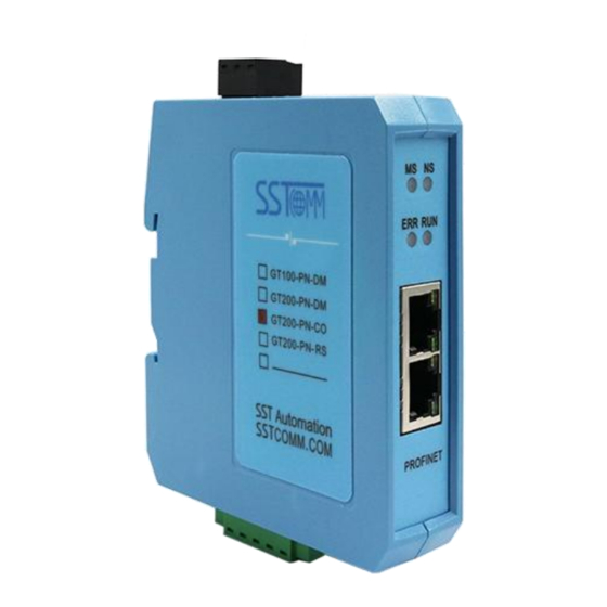
2 Hardware Descriptions 2.1 Product Appearance DIP Switch Network Status Indicator Power Interface Module Status Indicator CAN/CANopen Status Indicator PROFINET Interface CAN/CANopen Interface Note: This picture is for reference only. The product appearance is subject to the actual product. WWW.SSTAUTOMATION.COM... -
Page 12: Led Indicators
Green Off No data sending and receiving See below table See below table Note: GT200-PN-CO is in the configuration state, the ERROR and RUN indicators blinks alternately in orange. Module indicator and network indicator: Module indicator MS Network indicator NS... -
Page 13: Interface
On 1 2 Mode (Bit 1) Function (Bit 2) Description Run mode, configuration enabled Configuration Mode The module enters the update program state (customers cannot use this state) 2.4 Interface 2.4.1 Power Interface Function Power ground NC(Not Connected) +24V DC 2.4.2 Ethernet Interface The Ethernet interface uses RJ45 interface, follows the IEEE802.3u 100BASE-T standard, 10/100M adaptive. -
Page 14: Can/Canopen Interface
2.4.3 CAN/CANopen Interface CAN interface of GT100-CO-RS uses 5-pin connector: Wiring Pin 1 V+, 24VDC(optional) Pin 2 CAN-H Pin 3 Shield (optional) Pin 4 CAN-L Pin 5 GND, GND of 24V (optional) CAN-L CAN-H Shield Note: (1) Here, shield port is optional. The CAN-L and CAN-H must be connected. Here pin 1 and 5 are connected to the pin 3 and pin 1 of power port internally (Chapter 2.4.1). -
Page 15: Hardware Installation
3 Hardware Installation 3.1 Machine Dimension Size (width * height * depth): 1.0 in * 4.0 in * 3.6 in (25 mm * 100 mm * 90 mm) 3.2 Installation Method Using 1.4 in (35mm) DIN RAIL. WWW.SSTAUTOMATION.COM... -
Page 16: Quick Start Guide
7 Download the modeling configuration to the PLC; 8 Waiting for about 10s, GT200-PN-CO will establish PROFINET connection with the PLC. Note: How to find out how many GT200-PN-CO devices are in the LAN, including MAC address, IP address and name of devices. Users can see Chapter 4.4... -
Page 17: Software Configuration
4.2 Software Configuration There are two conditions for configuring the gateway. One is CANopen master mode, the other is CANopen slave mode or CAN mode. Users need to use two different software to configure the gateway. Use SST-CANopen-COM to configure the gateway under CANopen master mode. Use SST-TC-CFG to configure the gateway under CANopen slave or CAN mode. - Page 18 Step 4 In the mapping interface of the slave station, configure the object for PDO mapping, and click OK or Apply after configuration. Step 5 Double click GT200-PN-CO, add the slave in the scan list to the master list. WWW.SSTAUTOMATION.COM...
- Page 19 Step 6 Click Input and Output area, select TPDO and RPDO and finish the data mapping. Step 7 Configure the input and output bytes of PROFINET and CANopen parameters, and click download. WWW.SSTAUTOMATION.COM...
- Page 20 The following is the introduction for using SST-TC-CFG. Users can use SST-TC-CFG to easily complete the configuration of GT200-PN-CO, including IP address, subnet mask, gateway address, device name, baud rate of CANopen port, node number, SDO number, PDO number, CANopen data To PROFINET data mapping, CAN protocol type, baud rate of CAN and protocol, and PROFINET data mapping.
-
Page 21: Run
4.3 Run The data conversion between PROFINET network and CANopne/CAN of GT200-PN-CO is established by "mapping". GT200-PN-CO has two data buffers, one is input buffer (384/128 bytes); the other is output buffer (384/128 bytes). CANopen acts as a master Communication mode between CANopen and PROFINET is asynchronous mode, as shown below: PROFINET "Data 1"... - Page 22 The data in output buffer of GT200-PN-CO (PROFINET) is the data being mapped to RPDO or Download SDO commands of CANopen slave. Outputting mode of GT200-PN-CO is change of value, that is, until the PROFINET output data is changed, GT200-PN-CO transmits corresponding commands (RPDO or Download SDO) to CANopen network;...
- Page 23 PROFINET "Data 1" shows the data transfer process from PROFINET to CAN; "Data 2" shows the data transfer process from CAN to PROFINET. The gateway runs in CANopen network independently, and transmits read/write commands of CANopen parameters periodically according object dictionary, also transmits and receives PDO commands. When receiving I/O request from PROFINET, the gateway will instantly respond with the latest CANopen data to realize the matching of network speed.
- Page 24 CAN frame CAN frame If the GT200-PN-CO receives the CAN frame on the CAN network, the sequence number of the input frame is increased by 1. The customer can determine whether these CAN frames are needed according to their needs.
- Page 25 8-15 Byte Number of data Frame Sequence CAN frame Description 0xFF Reserved contained in header and number data CAN frame CAN frame Byte definition description in PROFINET IO 1. Byte0 - Byte3 are control bytes If the byte0 is zero, it means that the CAN frame of this sequence number is sent once; If the byte0 is not zero, it means that all CAN frames of this sequence number are sent periodically, The sending cycle is determined by the value of byte0, the sending cycle = the value of the byte0 * 10ms.
-
Page 26: Change Device Ip And Name
The lowest 8 bits of the frame header PROFINET Slave Presuming the input data length users have configured is N1, output data length is N2. GT200-PN-CO will periodically send the data within the address range of [0x0000, N1] to PROFINET network; When receiving data from PROFINET network, GT200-PN- CO will write the data to the address range of [0x0000, N2]. -
Page 27: Change Ip Info And Name
3. Click "Browse" and a dialog box will be shown as below: You can see that there is a device on the LAN, showing the it’s "IP address", "MAC address", "Device Name", "Gateway address" and "subnet mask". 4.4.2 Change IP Info and Name 1. - Page 28 After logging in, the MAC address of the device will be displayed in the box on the right side of "Target MAC". Modify IP address to "192.168.0.0.41", gateway address to "192.168.0.41", device name to "sst-100". The operation interface is as follows: If the modification is successful, the following dialog box will appear:...
-
Page 29: Ip Address Conflict Resolution
1 PROFINET device which has the same IP address and Device name on the same LAN when connecting many GT200-PN-CO devices. If the IP address and device name conflict, users can change IP address and device name of GT200-PN-CO according to Chapter "4.4.2 Change IP Info and Name"... - Page 30 You can see the IP address is reset to "0.0.0.0", choose the device and log in, the dialog box is shown as below: Set "IP", "Subnet" and "Gateway" to "192.168.0.18", "255.255.255.0" and "192.168.0.0" and you will see the below picture: WWW.SSTAUTOMATION.COM...
- Page 31 Click "OK". WWW.SSTAUTOMATION.COM...
-
Page 32: Software Instructions
5 Software Instructions 5.1 SST-TC-CFG SST-TC-CFG is the configuration software which can be used to configure GT200-PN-CO. It is based on Windows OS. Download the software on www.sstautomation.com and run the setup program to begin the installation. Please follow the prompts to install the software.
Need help?
Do you have a question about the GT200-PN-CO and is the answer not in the manual?
Questions and answers