
Related Manuals for SST Automation GT200-DP-DN


Summary of Contents for SST Automation GT200-DP-DN
- Page 1 DeviceNet/PROFIBUS DP Gateway GT200-DP-DN User Manual REV 4.1 SST Automation E-mail: SUPPORT@SSTCOMM.COM WWW.SSTCOMM.COM...
-
Page 2: Table Of Contents
GT200-DP-DN DeviceNet/PROFIBUS DP Gateway User Manual Catalog 1 About This Document..............................4 1.1 General................................4 1.2 Copyright Information............................ 4 1.3 Terms................................4 2 Product Overview..............................5 2.1 Product Function.............................5 2.2 Product Features............................. 5 2.3 Technical Specifications..........................5 2.4 Attention................................. 6 2.5 Related Products............................. 6 3 Hardware Descriptions.............................. - Page 3 GT200-DP-DN DeviceNet/PROFIBUS DP Gateway User Manual 10.2 Installation Method............................. 49 WWW.SSTCOMM.COM...
-
Page 4: About This Document
User Manual 1 About This Document 1.1 General This document describes every parameters of the gateway GT200-DP-DN and provides using methods and some announcements that help users use the gateway. Please read this document before using the gateway. 1.2 Copyright Information Copyright of this document reserved. -
Page 5: Product Overview
User Manual 2 Product Overview 2.1 Product Function GT200-DP-DN exchanges data between DeviceNet and PROFIBUS DP. It can connect a master device with DeviceNet interface to PROFIBUS DP master. 2.2 Product Features ▼Wide Application: Achieve the direct connection between DeviceNet network and PROFIBUS DP network. -
Page 6: Attention
GT200-DP-DN DeviceNet/PROFIBUS DP Gateway User Manual [10] Installation: 35mm rail; [11] Protection Level: IP20; 2.4 Attention To prevent stress, prevent module panel damage; To prevent bump, module may damage internal components; Power supply voltage control in the prospectus, within the scope of the requirements to burn module;... -
Page 7: Hardware Descriptions
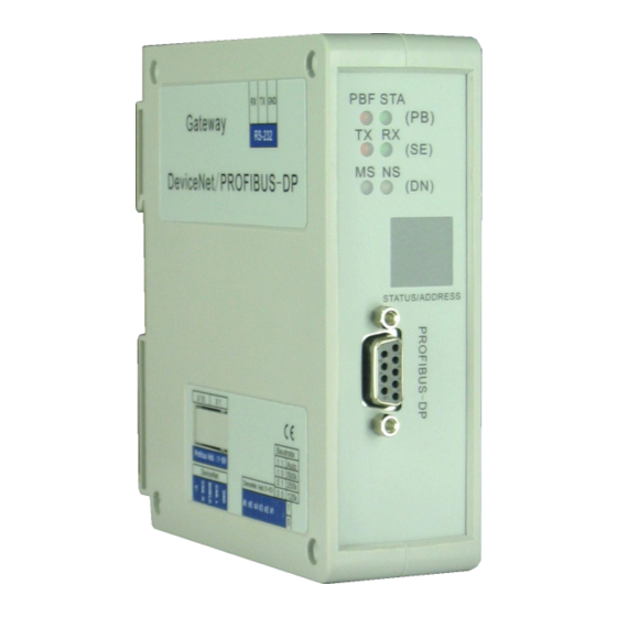
GT200-DP-DN DeviceNet/PROFIBUS DP Gateway User Manual 3 Hardware Descriptions 3.1 Product Appearance LED Indicators RS-232 port LED: Display network status and address Rotary Switch: Set PROFIBUS DP address PROFIBUS DP Interface DeviceNet Interface Switch: DeviceNet address and baud rate 3.2 Indicators... - Page 8 GT200-DP-DN DeviceNet/PROFIBUS DP Gateway User Manual DeviceNet Module Status Indicator (MS) Status Description No power supply or indicator may be bad Always Green Work properly Green Blinking Incorrect configuration, baud rate interception status Red Blinking Recoverable fault Always Red Unrecoverable fault...
-
Page 9: Configuration Switch
GT200-DP-DN DeviceNet/PROFIBUS DP Gateway User Manual 3.3 Configuration Switch Setting switch of PROFIBUS DP address: PROFIBUS DP address is calculated as: PROFIBUS DP Address=(A×10)+(B×1) DeviceNet address and DIP switch of baud rate instruction is shown below: 3-8 bits switches are the DeviceNet address setting switches, and they correspond with DeviceNet address #1bit - # 6bit. -
Page 10: Led
GT200-DP-DN DeviceNet/PROFIBUS DP Gateway User Manual 3.4 LED The main contents of LED include: DeviceNet address and PROFIBUS DP address. After powering on, LED successively display "pb", the current PROFIBUS DP address, "dn" and the current DeviceNet address. 3.5 Interface 3.5.1 DeviceNet Interface Wiring Instructions... -
Page 11: Profibus Dp Interface
Functions NC(Not connected) PROFI_B(Must be connected), Data positive PROFI_5V PROFI_A(Must be connected), Data negative 3.5.3 RS-232 Interface Configuration interface, and after connecting with computer, users can modify GT200-DP-DN configuration parameters through Hyper Terminal. Specific configuration steps, see Chapter 6. WWW.SSTCOMM.COM... -
Page 12: Run
DeviceNet device through POLL I/O write commands from Network Output Buffer. Input Buffer Output Buffer GT200-DP-DN not only acts as a DeviceNet slave node, as well as a PROFIBUS DP slave node, and needs to take up a node address of two networks. WWW.SSTCOMM.COM... -
Page 13: Quick Start Guide
User Manual 5 Quick Start Guide Use the following steps to apply your GT200-DP-DN: 1) According to the configuration steps to configure gateway, refer to chapter 6. 2) Setting PROFIBUS DP address through the rotary switch of the gateway, refer to chapter 3.3. -
Page 14: Gateway Configuration Instructions
Users can connect the gateway to PC through Gateway’s RS-232 interface and 232 direct cable (Together with the GT200-DP-DN to the client, one terminal end is 3-pin connector, and the other end is the DB9 connector) and configure the gateway through Hyper Terminal. Take all DIP switches of the gateway to off, and the value of the rotary code switches to 0, re-power the gateway and the gateway enter the configuration mode. -
Page 15: Main Menu
Item (3): Set data Swapping mode, No swapping, Two bytes swapping, and Four bytes swapping; Item (4): Set operating mode, Compatible mode (Support GT200-DP-DN V31) and Normal mode(GT200-DP-DN V41). Item (5): Display the current settings. Input and output bytes length of PROFIBUS DP and DeviceNet, Use the status word or not, Data exchange mode and product serial number, hardware version, firmware version;... -
Page 16: Show The Current Configuration
GT200-DP-DN DeviceNet/PROFIBUS DP Gateway User Manual 6.2.1 Show the Current Configuration Select 5 in the configuration main page, and it will show all current configuration. For the first time into the Hyper-Terminal configuration page, can view the configuration by selecting the option to determine what needs to be modified: 6.2.2 Set Input and Output Bytes... -
Page 17: Set Status Word
GT200-DP-DN DeviceNet/PROFIBUS DP Gateway User Manual When you need to change the settings, you can set input and output bytes through inserting the different number of bytes. The figure chooses 3, namely 48-byte input and output. 6.2.3 Set Status Word Select 2 in the configuration main page and it will show status word set options and current configurations. - Page 18 GT200-DP-DN DeviceNet/PROFIBUS DP Gateway User Manual As shown below: When you need to change the settings, you can follow the prompts, enter “y” for using status word, that is, the last two bytes of input data show the network status of another network. Enter "n" to disable it.
-
Page 19: Setting Data Exchange Methods
GT200-DP-DN DeviceNet/PROFIBUS DP Gateway User Manual 6.2.4 Setting Data Exchange Methods Select 3 in the configuration main page, shows data exchange options and all current configurations. As shown below: Option 1: No swapping; Option 2: Two bytes swapping; Option 3: Four bytes swapping;... -
Page 20: Setting Operation Modes
Selected 4 in the configuration main page and it will show operation mode options and current configurations. Option 1: Compatible mode (Support GT200-DP-DN V3.1 and user can use EDS file and GSD file of GT200-DP-DNV31); Option 2: Normal mode (GT200-DP-DN V4.1). - Page 21 GT200-DP-DN DeviceNet/PROFIBUS DP Gateway User Manual When select “2”, it select “Normal mode”. As the following picture shows: WWW.SSTCOMM.COM...
-
Page 22: Update Firmware
GT200-DP-DN DeviceNet/PROFIBUS DP Gateway User Manual 6.2.6 Update Firmware Select 6 in the main configuration page, it shows "Press y to enter the mode to update the firmware. Press any other key to exit". At this moment, enter "y" to enter the updating firmware mode, enter the other value can exit updating firmware. -
Page 23: Devicenet Network Configuration Instructions
GT200-DP-DN DeviceNet/PROFIBUS DP Gateway User Manual 7 DeviceNet Network Configuration Instructions After registering the GT200DPDN.EDS to DeviceNet configuration software, users can configure via the software. 7.1 EDS Register EDS(Electronic Data Sheet)is comprehensive description which supports DeviceNet network function. It equals to equipment’s driver of Windows. Users need install EDS files to DeviceNet network configuration software, such as RsNetWorx and so on, and then the configuration can be going on through network configuration software. - Page 24 GT200-DP-DN DeviceNet/PROFIBUS DP Gateway User Manual WWW.SSTCOMM.COM...
- Page 25 Step4: Install gateway GT200-DP-DN Shown as above, select “Register an EDS file”, as follow: Please register GT200-DP-DN.EDS file we provided, according to the place where you save EDS file, and select the file. Step 5: Select the file registering to choose...
- Page 26 GT200-DP-DN DeviceNet/PROFIBUS DP Gateway User Manual Click “NEXT”: Step 6: Select the icon. Following network configuration software will prompt you the equipment category in equipment storehouse, you may choose icon in this process. WWW.SSTCOMM.COM...
- Page 27 GT200-DP-DN DeviceNet/PROFIBUS DP Gateway User Manual Here, the device has successfully registered to the icon library location of configuration software’s equipment storehouse. WWW.SSTCOMM.COM...
-
Page 28: Devicenet Parameters Information
The following configuration demonstrates are in "Offline" status. From the device catalog, you can find the "DeviceNet / PROFIBUS DP Gateway" in "Vendor" (manufacturing number) and "SST Automation." directory, and drag it into the editing area, select the device WWW.SSTCOMM.COM... - Page 29 GT200-DP-DN DeviceNet/PROFIBUS DP Gateway User Manual address matching with the actual address, then double-click the device, you will see the following screen: You can also modify the device address. Click the "Parameter", then you can enter the parameter interface: WWW.SSTCOMM.COM...
- Page 30 GT200-DP-DN DeviceNet/PROFIBUS DP Gateway User Manual This is DeviceNet network configuration parameters interface of a device in RsNetWorx (GT200-DP-DN default configuration). Note: If you modify number of I/O bytes in the interface, you need re-power the gateway to take the modification effect.
- Page 31 DeviceNet is low-byte first, you need exchange the sequence of bytes. Some devices, such as PLC of GE which has data swapping function. Users can turn on this function according to their needs. GT200-DP-DN also has data swapping function; you can choose "No swapping", "Two bytes swapping" or "Four bytes swapping".
-
Page 32: Configure Plc's I/O Scan List
GT200-DP-DN DeviceNet/PROFIBUS DP Gateway User Manual Note: If the mapping data is multi-byte variable, which being transmitted by PROFIBUS DP is high-byte first, while being transmitted by DeviceNet is low-byte first. This is determined by protocol. Users may need to exchange data sequence. - Page 33 GT200-DP-DN DeviceNet/PROFIBUS DP Gateway User Manual Click Step two: In this interface, select the device being added to the scanning list, then click the arrow button, and then you can see: WWW.SSTCOMM.COM...
- Page 34 GT200-DP-DN DeviceNet/PROFIBUS DP Gateway User Manual Device is in the scan list of 1756-DNB DeviceNet Master. If you know how to configure the DeviceNet, you can click on the "Edit I / O Parameters ..." and modify parameters, or click the confirmation directly, and add all the devices to the scan list.
- Page 35 GT200-DP-DN DeviceNet/PROFIBUS DP Gateway User Manual Step three: Confirm input and output mapping. Users can see Input and Output Properties page; here is the settings on how DeviceNet I / O information of device be associated with 1756DNB memory. Generally use the default settings (Auto-map).
- Page 36 GT200-DP-DN DeviceNet/PROFIBUS DP Gateway User Manual Step Four: Download the appropriate scan list to 1756DNB according to the prompts. Step Five: Preparing corresponding program, download it to ControlLogix, then change the PLC state to run, if the be in the programming status, PLC take DeviceNet I / O scanning, cannot output data (IDLE), but only can input data.
-
Page 37: Select Online Path
GT200-DP-DN DeviceNet/PROFIBUS DP Gateway User Manual 7.4 Select Online Path From offline to online, users need to select the path. According to actual configuration options, users can select the path, the next map is using serial port (DF1) . WWW.SSTCOMM.COM... - Page 38 GT200-DP-DN DeviceNet/PROFIBUS DP Gateway User Manual Users have any further questions, please reference RsNetWorx user manual. WWW.SSTCOMM.COM...
-
Page 39: Profibus Dp Network Configuration Instruction
DeviceNet/PROFIBUS DP Gateway User Manual PROFIBUS Network Configuration Instruction The following content explains how to use STEP7 to set GT200-DP-DN. First, copy *.gsd file to the following path: Step7\S7data\gsd\ 1. Open SIMATIC Manager 2. Click File->New, create a new file: WWW.SSTCOMM.COM... - Page 40 GT200-DP-DN DeviceNet/PROFIBUS DP Gateway User Manual 3. Insert->Station->SIMATIC 300 Stations: 4. Open S7 PLC hardware configuration: SIMATIC 300(1) ->Hardware, double click: 5. Click Options-> Install GSD File, and install GSD of GT200-DP-DN: WWW.SSTCOMM.COM...
- Page 41 Copy the GSD file in the relevant directory, select and register, you can find your registered device in the hardware configuration interface, the right the window of the hardware configuration interface/ PROFIBUS DP / Additional Field Devices/Converter/GT200-DP-DN, as shown as below: WWW.SSTCOMM.COM...
- Page 42 GT200-DP-DN DeviceNet/PROFIBUS DP Gateway User Manual 6. Set PLC rack, double-click “Hardware Catalog\SIMATIC 300\RACK-300\Rail”: WWW.SSTCOMM.COM...
- Page 43 GT200-DP-DN DeviceNet/PROFIBUS DP Gateway User Manual 7. Set CPU module, choose the corresponding device types and the occupied slots; 8. Create PROFIBUS DP network, set PROFIBUS DP: New->Network settings, choose “DP”, choose a kind of baud rate as 187.5Kbps, then click “OK”. Double-click it:...
- Page 44 GT200-DP-DN DeviceNet/PROFIBUS DP Gateway User Manual 9. Choose address of PROFIBUS Master station: Select PROFIBUS Address WWW.SSTCOMM.COM...
- Page 45 Operation includes two steps. The first step is moving GT200-DP-DN to the left and up area, (PROFIBUS DP bus), the mouse will change sharp, it means you can move it in. The second step is moving data to left and down data mapping table, (PLC memory).
- Page 46 GT200-DP-DN DeviceNet/PROFIBUS DP Gateway User Manual The factory configuration of number of bytes is "48 Byte In, 48 Byte Out". Note: Slave station’s address should be the same with the setting of module’s dial switches! 11. As shown above, right-click input and output mapping of the slot, set the relevant property, as shown below: You can set input and output mapping area start address in the page.
-
Page 47: How Step7 Read And Write Gateway Data
GT200-DP-DN DeviceNet/PROFIBUS DP Gateway User Manual 9 How Step7 read and write Gateway Data Data blocks which use “Total Length” as “consistent” are shown as follow: 2 Words Input Consistent 4 Words Input Consistent 8 Words Input Consistent 16 Words Input Consistent... - Page 48 GT200-DP-DN DeviceNet/PROFIBUS DP Gateway User Manual Data blocks which use “Words” as “consistent” are shown as follow: In Step7 program, you can use “MOVE” instruction read and write data. WWW.SSTCOMM.COM...
-
Page 49: Installation
GT200-DP-DN DeviceNet/PROFIBUS DP Gateway User Manual 10 Installation 10.1 Machine Dimension Size: 1.57 in (width)*4.92 in (height)*4.33 in (depth) 10.2 Installation Method 35mm DIN rail WWW.SSTCOMM.COM... - Page 50 GT200-DP-DN DeviceNet/PROFIBUS DP Gateway User Manual WWW.SSTCOMM.COM...
Need help?
Do you have a question about the GT200-DP-DN and is the answer not in the manual?
Questions and answers