SST Automation GT200-HT-MT User Manual
Hart / modbus tcp gateway
Hide thumbs
Also See for GT200-HT-MT:
- User manual (74 pages) ,
- User manual (46 pages) ,
- User manual (48 pages)

Related Manuals for SST Automation GT200-HT-MT


Summary of Contents for SST Automation GT200-HT-MT
- Page 1 HART / Modbus TCP Gateway GT200-HT-MT User Manual V 4.0 Rev A SST Automation Email: support@sstautomation.com www.SSTAutomation.com...
- Page 2 Important Information Warning The data and examples in this manual cannot be copied without authorization. SST Automation reserves the right to upgrade the product without notifying users. The product has many applications. The users must make sure that all operations and results are in accordance with the safety of relevant fields, and the safety includes laws, rules, codes and standards.
-
Page 3: Table Of Contents
2.6 Interfaces ................................ 7 2.6.1 Power Interface ........................... 7 2.6.2 Ethernet Interface ..........................7 2.6.3 HART Interface ........................... 7 2.7 Topology of GT200-HT-MT and HART Instruments ..................8 2.7.1 Point-to-Point Wiring .......................... 9 2.7.2 Multi-Drop Wiring ..........................11 3 Hardware Installation .............................. 16 3.1 Mechanical Dimensions .......................... - Page 4 5.5.6 Scan ..............................43 5.5.7 Modify Device ID ..........................45 5.5.8 Conversion Tools ..........................45 5.5.9 Hardware Communication ........................ 46 5.5.10 Open/Save Project ........................... 47 5.5.11 Export Excel ............................ 48 6 Interface Design Description ...........................49 6.1 Data Exchange ..............................49 6.1.1 Modbus TCP Register Address Mapping ..................50 6.2 Flowchart for Executing a HART Command ....................
-
Page 5: Product Overview
Clients. It can connect up to 15 HART slave devices to up to 4 Modbus TCP Clients to easily read and write data between HART and Modbus TCP. On the HART side, the GT200-HT-MT can be configured as a primary or secondary master, and on the Ethernet side it functions as a Modbus TCP Server. - Page 6 [8] Each HART command can be configured for change-of-state output, polling output, initialization output or disable output. [9] HART channels support up to 127 user commands, a mix of basic and advanced modes, with a maximum of 30 commands in advanced mode, HART output data buffers up to 1000 bytes and input data buffers up to 1600 bytes.
-
Page 7: Related Products
GT200-HT-RS GT200-3HT-MT GT200-3HT-RS GT100-HT-EI To get more information about related products, please visit SST Automation’s website: www.sstautomation.com. 1.5 Revision History Revision Date Chapter Description Fixed the node points for the Point-to-Point wiring diagrams in Chapter 2.7.1 Added external HART resistor examples Chapters 2.7.1, 2.7.2,... -
Page 8: Hardware Description
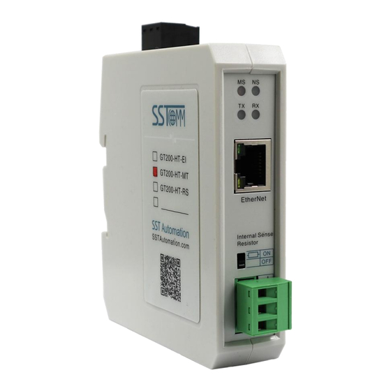
2 Hardware Description 2.1 Product Appearance Firmware Button Power Interface DIP Switch Ethernet Indicators 灯 HART Indicators Ethernet Interface Resistor Switch HART Interface Note: This picture is for reference only. The product appearance is subject to the actual product. www.SSTAutomation.com... -
Page 9: Led Indicators
2.2 LED Indicators Indicator State Description Green blinking HART data transmitting Green off No data transmitting Green blinking HART data receiving Green off No data receiving Modbus TCP connection is established. Green on Communication is normal. Green blinking Modbus TCP connection is not established. Red off Module status: IP address starts normally Static IP... -
Page 10: Configuration Dip Switch
2.5 Internal Series Resistor Switch The GT200-HT-MT has an internal series resistor (270 Ohm /2 W) required for the HART channel. This allows up to 13 HART instruments to be connected. When the power going through the series resistor is more than 2W, you must use an external series resistor (250 Ohm /3 W) which allows the gateway to be connected to up to 15 HART instruments. -
Page 11: Interfaces
2.6 Interfaces 2.6.1 Power Interface GT200-HT-MT has one power interface, and it is recommended to use a 24V DC power supply. Description Power GND NC (Not Connected) 24V+, DC 24V+ 2.6.2 Ethernet Interface The Ethernet interface uses RJ45 interface, follows the IEEE802.3u 100BASE-T standard. -
Page 12: Topology Of Gt200-Ht-Mt And Hart Instruments
HART at this time. It is recommended to use the separate power supply for the HART instruments and the GT200-HT-MT, to ensure stable communication. To improve the communication efficiency of the field bus, it is recommended not to configure empty nodes or unused commands in the SST-HI-CFG configuration software. -
Page 13: Point-To-Point Wiring
2.7.1 Point-to-Point Wiring The following are the topologies for two wire and four wire point-to-point wiring. www.SSTAutomation.com... - Page 14 www.SSTAutomation.com...
-
Page 15: Multi-Drop Wiring
2.7.2 Multi-Drop Wiring The following are the topologies for two wire and four wire multi-drop wiring. Two wire – When using the internal resistor: www.SSTAutomation.com... - Page 16 Two wire – When using an external resistor: www.SSTAutomation.com...
- Page 17 Two wire – When using an external resistor: www.SSTAutomation.com...
- Page 18 Four wire – When using the internal resistor: www.SSTAutomation.com...
- Page 19 Four wire – When using an external resistor: www.SSTAutomation.com...
-
Page 20: Hardware Installation
3 Hardware Installation 3.1 Mechanical Dimensions Size (width * height * depth): 1.0 in * 4.0 in * 3.6 in (25 mm * 100 mm * 90 mm) 3.2 Installation Method Using 1.4 in (35mm) DIN RAIL. www.SSTAutomation.com... -
Page 21: Quick Start Guide
4 Quick Start Guide 4.1 Hardware Connection Make sure the GT200-HT-MT is in the appropriate operating mode that allows for configuration. Set the gateway to Configuration Mode by settings the DIP switches to 1-OFF, 2-ON while the gateway is powered off. -
Page 22: Software Configuration
4.2 Software Configuration SST-HI-CFG is a Windows-based platform, used to configure GT200-HT-EI and GT200-HT-MT. Open the SST-HI-CFG software installed in your computer and select "GT200-HT-MT". Click “Ethernet” on the left, and set the Ethernet parameter. The Modbus TCP Server relevant parameters are configured as follows: www.SSTAutomation.com... - Page 23 Select “HART Channel” on the left and set the HART channel parameters. As shown below, the GT200-HT-MT is configured as the primary master and using the point-to-point mode. Note: The HART protocol specifies that devices with slave address 0 work in point-to-point mode, and this allows HART signals and an analog 4-20mA signal to exist at the same time.
- Page 24 You can either click "Click to add a command", select "Node (0)" and click "Add Cmd" in the toolbar, or right-click "Node (0)" and click "Add command" to add a command in the corresponding node. In the pop-up dialog box, add command ID1 by double-clicking or selecting and clicking ">>", and click OK”. www.SSTAutomation.com...
- Page 25 Click “Command ID1”. The configuration of the HART commands (Basic and Advanced) are shown below: To read the Primary Variable, move Bytes 1-4 (primary variable) to the mapping address section of the window. This allows the data to be received and read at the specified Modbus register address. www.SSTAutomation.com...
- Page 26 Click on the icon , select the gateway in the pop-up dialog box and click on "Download", then click on "Download Configuration". www.SSTAutomation.com...
-
Page 27: Common Hart Commands
4.3 Common HART Commands The following is a short list of useful HART commands that can be used for common applications of most HART devices. More information about supported commands is available from FieldComm Group at the following link: https://library.fieldcommgroup.org/20127/TS20127/7.2/ Note: The front two bytes of the actual response data is the status info of the device. - Page 28 Command 1 (Command ID1): Read Primary Variable Returns the primary variable value in float data type. Request: None Response: Byte Description Byte 0 Primary Variable Units Byte 1-4 Primary Variable An example of this command in the SST configuration software is shown below: As the request is “None”, the user should fill “0”...
- Page 29 Command 3 (Command ID 3): Read Dynamic Variable and Primary Variable Current Reads the primary variable current and four (at most) pre-defined dynamic variables. The primary variable current always matches the AO output current of the device. A second, third and fourth variable is defined for each device type, E.g.
- Page 30 If the user does not need to map all the variables to the Modbus TCP registers, please follow the guide below. Switch to the “Advanced Configuration Mode”, click the “Configuration” button, and only select the variable(s) needed. In this example, only the “Primary Variable” and the “Secondary Variable” are selected. Note: Selected variables are listed in the left table.
- Page 31 Command 6 (Command ID6): Write Polling Address Writes the polling address (HART slave address) to the field device. Request: Byte Description Byte 0 Polling Address (Between 0-15) Byte 1 (Only on supported HART devices) Loop Current Mode (0=Disabled, 1=Enabled) Response: Byte Description Byte 0...
-
Page 32: Software Instructions
5 Software Instructions 5.1 Main Interface The software interface includes: Title Bar, Menu Bar, Toolbar, Configuration Window and Tree View. Note: The gray parameters cannot be changed. Title Bar Menu Bar Toolbar Configuration Window Tree View Comment Interface www.SSTAutomation.com... -
Page 33: Toolbar
5.2 Toolbar The toolbar is shown as below: The toolbar provides icon shortcuts to major functions. New: Create a new configuration project. Save: Save the current configuration. Open: Open a configuration project. Add Node: Add a HART node. Delete Node: Delete a HART node. Add Command: Add a HART command. -
Page 34: Comments Interface
5.3 Comments Interface The comments interface displays the explanation of the corresponding configuration item. For example, when selecting "Mode of Outputting Commands", the comments interface is as below: www.SSTAutomation.com... -
Page 35: Tree View Operations
5.4 Tree View Operations 5.4.1 Edit the Items in the Left Tree View Users can edit the items in the left tree view three different ways: 1. Edit with the commands in the menu. 2. Edit with the icon in the toolbar. Please see "Toolbar" chapter for details. 3. -
Page 36: Hart Node And Command Operations
5.4.2 HART Node and Command Operations Users can edit HART nodes and commands by three operation ways in the "Tree View Operations" chapter. 1. Add node: Select the "HART Channel" and add a new node. A new node named "Node-X" will be added under the HART Channel. -
Page 37: The Operation Of Configuration Interface
Click the Ethernet in the equipment view interface, this will display the configuration view interface as follows: Assign IP Mode: Manually Assign, DHCP IP Address: Set the IP address of the device. Subnet Mask: Set the subnet mask of GT200-HT-MT. Default Gateway: Set the network gateway address of the device. DNS1/ DNS2: Reserved. - Page 38 Starting Address of Read-Only Register (Input Data): The gateway is used as Modbus TCP server to support the client to read the starting address of the input data using the 04/03 function code. It is necessary to fill in the protocol address (base 0) format here, and displayed in decimal. Range 0-64736. For example: 04 function code: The PLC address format is 30001, then you need to fill in it as the protocol address format 0.
-
Page 39: Hart Configuration
5.5.2 HART Configuration 5.5.2.1 HART Channel Configuration View Click the HART Channel in the equipment view interface, this will display the configuration view interface as follows: HART Master Type: Primary master, Secondary master HART Networks: Supports two HART Network: Point-to-Point and Multi-drop. The gateway can communicate with the HART slave device with 0 as its address in Point-to-Point mode. - Page 40 5.5.2.2 Node Configuration Choose to click "Click to add a node" or select "HART Channel" and click "Add Node" in the toolbar, or right-click "HART Channel" and click "Add Node" to add nodes in the HART channel. In the HART Channel, after adding a node, select the node: HART Slave Address: "Point-to-Point"...
- Page 41 5.5.2.3 Command Configuration Choose to click "Click to add a node" or select "HART Channel" and click "Add Node" in the toolbar, or right-click "HART Channel" and click "Add Node" to add nodes in the HART channel. After adding commands under a node, select the command: Configuration Mode: Basic and Advanced (2 available options).
- Page 42 Memory Starting Address of Sending Data: Set the memory starting address of output data by this command, the range is 3000-3255. Modbus TCP Starting Address of Sending Data: The starting address of the Modbus TCP master station to send data: 3000-3255. Length of Sending Data (BYTE): Used to set the length of output data by this command.
-
Page 43: Conflict Detection
5.5.3 Conflict Detection The data is stored in the gateway’s buffer. To check if there are conflicts in the data mapping address, open the conflict detection window by clicking the "Conflict" icon. Each grid represents one byte address. Green: Read command is shown in input mapping area, it will be in green without conflict. Yellow: Write command: When the address mapping area is located in the input area, it will be in yellow without conflict. -
Page 44: Show Memory Data
HART fieldbus. The operating steps are as follows: 1) Ensure that the GT200-HT-MT’s function bit of configuration switch is in the ON state and the mode bit of configuration switch is in the OFF state, restart the gateway. Then the GT200-HT-MT is in the debug mode. -
Page 45: Diagnose
Steps are as follows: 1) Ensure that the GT200-HT-MT’s function bit of configuration switch is in the ON state and the mode bit of configuration switch is in the OFF state, restart the gateway. GT200-HT-MT is in the debug mode. - Page 46 Click Node (x), it is shown as below: It shows the response status of the configured commands. Click "Refresh" this will refresh these command status, "Periodically refresh" will refresh the command status once. Double clicking the commands will show their command information, command ID03 can start data input. www.SSTAutomation.com...
-
Page 47: Scan
The slave scan function can help users to check the HART slave address and modify the slave address. Steps are as follows: Set the configuration DIP switch on the GT200-HT-MT to 1-ON 2-OFF, which will set the gateway into debug mode. - Page 48 Click "Start" in "Slave Scan" interface, it will show the short address, long address and ID of HART slave devices which are connected to the gateway. Move to the relevant device and right click it, and click "Modify Slave Address" will show the "Modify slave address"...
-
Page 49: Modify Device Id
5.5.7 Modify Device ID The modify device ID function can help users to check the Device ID, let the user know the currently selected GT200-HT-MT device ID value, and can modify the value. Steps are as follows: 1) Turn the GT200-HT-MT configuration (operation) DIP switch to "ON", and then power on again. -
Page 50: Hardware Communication
5.5.9 Hardware Communication 5.5.9.1 Ethernet Configuration The hardware communication menu items are as follows: 5.5.9.2 Upload Configuration Choose upload configuration, it will pop up the dialog box of searching equipment: Select the equipment you want to configure and click "Upload" to enter into the upload dialog box. www.SSTAutomation.com... -
Page 51: Open/Save Project
5.5.9.3 Download Configuration The operation of download configuration is the same as upload configuration: Note: Before downloading, please confirm all configurations have been completed and right. 5.5.10 Open/Save Project Select "Open" to open an existing configuration project: Select "Save" or "Save As..." to save the configuration project as a *.xml file. www.SSTAutomation.com... -
Page 52: Export Excel
5.5.11 Export Excel The configuration can be exported as a table. Please confirm that Microsoft Excel is installed on your computer before using this function. www.SSTAutomation.com... -
Page 53: Interface Design Description
Data exchange between HART and Modbus TCP via the GT200-HT-MT is defined through “data mapping”. When data is read or written, it is initially stored in the internal memory buffer of the GT200-HT-MT before being transmitted between HART and Modbus TCP. There are two internal data buffer areas in the GT200-HT-MT: One is the Modbus TCP network input buffer and the other is the Modbus TCP network output buffer. -
Page 54: Modbus Tcp Register Address Mapping
For more details on setting the the function code mode and starting addresses, see Chapter 5.5.1. When the function code mode of the GT200-HT-MT is configured to "04 Read Input Data, 03 Read Back Output Data" and the starting addresses are set to "0", function code 04 is used on the Modbus TCP Client to read the HART response data from the gateway. - Page 55 When the function code mode of the GT200-HT-MT is configured to "03 Read Input Data, 04 Read Back Output Data" and the starting addresses are set to "0", function code 03 is used on the Modbus TCP Client to read the HART response data from the gateway.
-
Page 56: Flowchart For Executing A Hart Command
6.2 Flowchart for Executing a HART Command www.SSTAutomation.com... -
Page 57: How To Connect To A Modbus Tcp Client
7 How to Connect to a Modbus TCP Client The GT200-HT-MT gateway allows HART instruments to communicate with Modbus TCP Clients in a Modbus TCP network by having the gateway function as a Modbus TCP Server. The following example illustrates how the gateway communicates with a Modbus TCP Client by using Modbus Poll (Modbus TCP Client emulation software). - Page 58 Command ID1: Read primary variable (PV) Returns the value of the primary variable as a floating-point type Request: None Response: Byte Description Byte 0 Primary Variable Units Byte 1-4 Primary Variable www.SSTAutomation.com...
- Page 59 (2) When configuring HART command ID3, use the advanced function to configure the primary variable (PV), the secondary variable (SV), and the tertiary variable (TV). Command ID3: Reads four (predefined) dynamic variables and the primary variable current Reads the primary variable current and 4 (at most) pre-defined dynamic variables, the primary variable current always matches the device's AO output current.
- Page 60 (3) The configuration of HART Command ID6 is used to modify the address of the HART device. Command ID6: Write POLLING address This is the data link layer management command. This command writes the Polling address and loop current mode to the field device. Request: Byte Description...
- Page 61 Function codes 06/16 are used to write the HART request data to the gateway. Modbus register 4x0000 corresponds to the Polling address and loop current mode of the requested device of HART Command ID6. Modbus TCP GT200-HT-MT HART Response Register Address...
- Page 62 Modbus TCP GT200-HT-MT HART Request Register Address Output Buffer Address Read: Function Code 03 Write: FC06/FC16 Command ID6 Polling Address 3000 (Byte 0) 4x0000 Command ID6 Loop Current Mode 3001 (Byte 1) www.SSTAutomation.com...
- Page 63 3. Use Modbus Poll to connect to the gateway and read/write data with the following configuration: Note: The gateway acts as Modbus TCP Server. Use the Modbus Poll software as a Modbus Client to connect to the gateway. The gateway supports using either function codes 03 or 04 (configured in SST-HI-CFG) to read data from HART devices.
- Page 64 4. Use Modbus POLL to read data (3x0000-3x0009) and write data via 4x0000. The data in the gateway buffer can be viewed in (refer to Chapter 5.5.4) and the actual floating-point data of the HART device can be viewed via (refer to Chapter 5.5.5).
Need help?
Do you have a question about the GT200-HT-MT and is the answer not in the manual?
Questions and answers