
Related Manuals for SST Automation GT200-EI-2RS485


Summary of Contents for SST Automation GT200-EI-2RS485
- Page 1 Modbus / EtherNet/IP Gateway GT200-EI-2RS485 User Manual V 3.3 SST Automation Email: support@sstautomation.com www.SSTAutomation.com...
- Page 2 The product has many applications. The users must make sure that all operations and results are in accordance with the safety of relevant fields, and the safety includes laws, rules, codes and standards. Copyright Copyright © 2022 by SST Automation. All rights reserved. Trademark is the registered trade mark of SST Automation.
-
Page 3: Table Of Contents
GT200-EI-2RS485 Modbus/EtherNet/IP Gateway User Manual Catalog 1 Product Overview ..............................1 1.1 Product Function ............................1 1.2 Feature ................................1 1.3 Technical specification ........................... 1 1.4 Revision History .............................2 2 Hardware Description ..............................3 2.1 Appearance ..............................3 2.2 LED Indicators ............................... 4 2.3 Configuration Switch ............................. - Page 4 GT200-EI-2RS485 Modbus/EtherNet/IP Gateway User Manual 5.6.3 Download ............................19 5.7 Load and Save Configuration ........................19 5.7.1 Load Configuration Project .......................19 5.7.2 Save Configuration Project ....................... 20 5.8 Export Excel ..............................20 5.9 Debug ................................20 6 EtherNet/IP Connection Parameters ........................22 7 How to Read/Write I/O Data ...........................23...
-
Page 5: Product Overview
115200; parity mode support: none, odd, even, mark, space; 1 or 2 stop bits; [6] GT200-EI-2RS485 acts as master at the side of Modbus network and supports 01H, 02H, 03H, 04H, 05H, 06H, 0FH, 10H function codes, can be configured up to 48 Modbus commands for each RS-485 interface;... -
Page 6: Revision History
GT200-EI-2RS485 Modbus/EtherNet/IP Gateway User Manual the problem of data format between two different networks; [7] Two independent RS-485 interfaces with 1KV optical isolation; [8] The maximum number of input and output bytes of EtherNet/IP: Maximum number of input bytes: 492Bytes Maximum number of output bytes: 492Bytes [9] Power supply: 24VDC (9V ~ 30V), 90mA (24VDC);... -
Page 7: Hardware Description
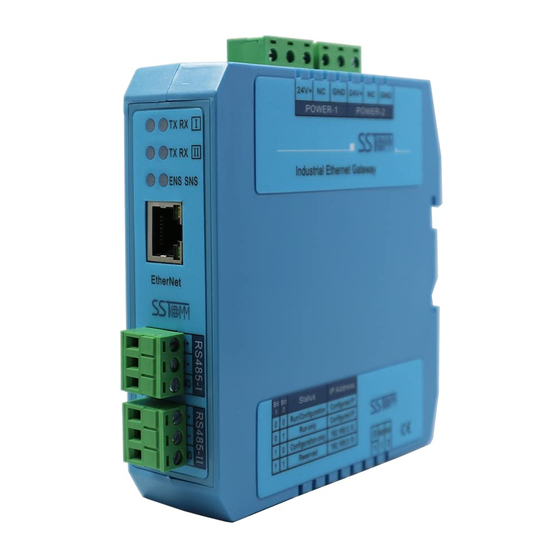
GT200-EI-2RS485 Modbus/EtherNet/IP Gateway User Manual 2 Hardware Description 2.1 Appearance Dual Power Interface LED Indicators Ethernet RJ-45 Interface RS-485-I Interface RS-485-II Interface Configuration Switch Notes: This picture is for reference only. The product appearance is subject to the actual product. -
Page 8: Led Indicators
EtherNet/IP and Modbus network. Notes: If you changed the DIP switch, you have to restart GT200-EI-2RS485 (power off and power on) to make the settings take effect. -
Page 9: Interface
GT200-EI-2RS485 Modbus/EtherNet/IP Gateway User Manual 2.4 Interface 2.4.1 Power Interface GT200-EI-2RS485 has two power interfaces, with power redundancy function, when one the way to power failure, power can continue to supply the other way. 24V+ Function GND, NC, no connection 24V+ , DC 2.4.2 Ethernet Interface... -
Page 10: Rs-485 Interface
GT200-EI-2RS485 Modbus/EtherNet/IP Gateway User Manual 2.4.3 RS-485 Interface Serial interface uses 3-pin pluggable terminal and users can wire it according to the wiring instructions on the panel. Function B(+), RS-485 A(-), RS-485 www.SSTAutomation.com... -
Page 11: Hardware Installation
GT200-EI-2RS485 Modbus/EtherNet/IP Gateway User Manual 3 Hardware Installation 3.1 Mechanical Dimensions 1.33in * 4.56in * 4.21in (34mm * 116mm * 107.4mm) www.SSTAutomation.com... -
Page 12: Installation Method
GT200-EI-2RS485 Modbus/EtherNet/IP Gateway User Manual 3.2 Installation Method Using 1.4 in (35mm) DIN RAIL. www.SSTAutomation.com... -
Page 13: How To Start
GT200-EI-2RS485 Modbus/EtherNet/IP Gateway User Manual 4 How to Start 4.1 Connect to the Power DC 24V power supply, dual power supply interface, a redundant function, users can use one or two power supply. If you are using two power supply, when the way in which the power fails, the other way you can continue to supply power to ensure normal operation. -
Page 14: Ethernet Connection
120Ω 1/2W. Notes: There is no internal termination resistor in the RS-485 interface of GT200-EI-2RS485. 4.3 Ethernet Connection Connect the GT200-EI-2RS485 to your computer with the Ethernet cable, in the RJ-45 port. www.SSTAutomation.com... -
Page 15: Configuration Switch
192.168.0.1. If the Assign IP mode is DHCP, and there is no DHCP Server or you can’t search the GT200-EI-2RS485. You can set mode bit (bit 1) to On, and restart GT200-EI-2RS485 (power off and power on), then the fixed IP address of GT200-EI-2RS485 is 192.168.0.10, subnet mask is 255.255.255.0, gateway address is 192.168.0.1. -
Page 16: Configuration Software
5 Configuration Software 5.1 Notes before Configuration SST-GT-CFG is a product based on Windows platform, and used to configure GT200-EI-2RS485. It can set related parameters and commands of Modbus and other bus. The document mainly introduces the use method of GT200-EI-2RS485. - Page 17 GT200-EI-2RS485 Modbus/EtherNet/IP Gateway User Manual Title Bar Menu Bar Toolbar Tree View Configuration Window Comment Interface Tool bar interface is shown as below: New: Create a new configuration project. Save: Save the configuration project. Open: Open the configuration project. Add Node: Add a Modbus slave node.
-
Page 18: Operation Of Devices View
GT200-EI-2RS485 Modbus/EtherNet/IP Gateway User Manual Upload: Read the configuration information from the module and shown in the software. Download: Download the configuration file to the gateway. AutoMap: Used to automatically calculate the mapped memory address without confliction by each command. -
Page 19: Operation Types
GT200-EI-2RS485 Modbus/EtherNet/IP Gateway User Manual 5.3.3 Operation types 1. Add nodes: Right click on subnet or existing nodes, and then perform the operation of adding a new node. Then there is a new node named "new node" under subnet. 2. Delete nodes: Right click on the node to be deleted, and then perform the operation of deleting the node. The node and its all commands will be deleted. -
Page 20: Operation Of Configuration View
GT200-EI-2RS485 Modbus/EtherNet/IP Gateway User Manual 5.4 Operation of Configuration View 5.4.1 Ethernet Configuration In the interface of device view, click Ethernet, and then the configuration view is shown as follows: Configurable items include: Assign IP Mode, IP Address, Subnet Mask, Gateway Address, DNS1, DNS2. - Page 21 GT200-EI-2RS485 Modbus/EtherNet/IP Gateway User Manual Baud Rate: There are 300, 600, 1200, 2400, 9600, 19200, 38400, 57600 and 115200bps to be selected. Data bits: 8 bits Parity: There are none, odd, even, mark and space to be selected. Stop Bits: There are 1 and 2 to be selected.
-
Page 22: Node Configuration
GT200-EI-2RS485 Modbus/EtherNet/IP Gateway User Manual 5.4.3 Node Configuration In the interface of device view, left click a node and then configuration interface is shown as follow: 5.4.4 Command Configuration In the interface of device view, left click a command and then configuration interface is shown as follow: Starting Address: The starting address of register or switching value or loop and so on in Modbus slave and the range is 0~65535. -
Page 23: Conflict Detection
GT200-EI-2RS485 Modbus/EtherNet/IP Gateway User Manual When write command is used exchanging locally, it also can use: 0x0000 ~ 0x01FF Mapping Bit: For the bit operation commands, the position range of start-bit byte is 0 ~ 7. Bytes Swap: There are three kinds of type, No swapping, two bytes swapping, four bytes swapping. The byte display order of Modbus and Profibus-DP is MSB being preferential;... -
Page 24: Operation Of Memory Mapping Area
GT200-EI-2RS485 Modbus/EtherNet/IP Gateway User Manual remove the selected box and it doesn’t show the mapping location. The function can be used to conflict detect of memory-mapping area. 5.5.2 Operation of Memory Mapping Area Memory mapping area is divided two parts: input area and output area. -
Page 25: Hardware Communication
GT200-EI-2RS485 Modbus/EtherNet/IP Gateway User Manual 5.6 Hardware Communication Hardware communications' menu items are shown as follow: 5.6.1 Ethernet Configuration Users can choose whether to use the search function. When users use the search feature, upload or download configuration when you can search for all Ethernet equipment ENB302-MI; when the user does not use the search feature, users must specify their own devices to connect to, in the configuration when the upload or download only lists the devices. -
Page 26: Upload
GT200-EI-2RS485 Modbus/EtherNet/IP Gateway User Manual 5.6.2 Upload Choose to upload configuration dialog box will pop up the search appliance: Select the device you want to configure and click "Log In". Gateway configuration information will be uploaded to the software from the device. The pop-up window is as follows:... -
Page 27: Download
GT200-EI-2RS485 Modbus/EtherNet/IP Gateway User Manual 5.6.3 Download Download configuration and upload configuration similarly: Notes: Before downloading, make sure all the configuration has been completed and correct. 5.7 Load and Save Configuration 5.7.1 Load Configuration Project Select “Open” and then you can open a project:... -
Page 28: Save Configuration Project
GT200-EI-2RS485 Modbus/EtherNet/IP Gateway User Manual 5.7.2 Save Configuration Project Select “Save” can save the project: 5.8 Export Excel Excel document helps users to examine the configuration related. Choose the icon , save the configuration as excel document and choose the right path. - Page 29 GT200-EI-2RS485 Modbus/EtherNet/IP Gateway User Manual Select the device and click "Log In", then enter the debug dialog. Display interface as follows: Memory-mapped address: Memory starting address of writing data in the gateway Data: Data being written to memory of gateway Users can debug Modbus communication through transmitting data.
-
Page 30: Ethernet/Ip Connection Parameters
GT200-EI-2RS485 Modbus/EtherNet/IP Gateway User Manual 6 EtherNet/IP Connection Parameters Connection parameters the adapter provides are as below: Data Size 128 Bytes 256 Bytes 492 Bytes Parameters Input Instance Output Instance Configuration Instance Notes: The Input data size should include 4-byte status. For example, when using the 256-byte parameters, the input size should be 260 bytes. -
Page 31: How To Read/Write I/O Data
GT200-EI-2RS485 Modbus/EtherNet/IP Gateway User Manual 7 How to Read/Write I/O Data The following RSLogix 5000 example will describe how to read/write I/O data. 7.1 Read/Write Data by IO Messaging (Recommend) Right click on EtherNet/IP scanner module, click "New Module", as shown below: In the pop-up dialog box, unfold "+"... - Page 32 GT200-EI-2RS485 Modbus/EtherNet/IP Gateway User Manual Configure relevant information in the pop-up window, as shown below: Set Communication Parameters. Please refer to chapter 6. Set the name. IP address of the SST gateway. In the above picture, the module information needs to be configured includes: Name: Name the added EtherNet/IP adapter module.
- Page 33 Comm Format: Configure data types. Users can choose data types as DINT, INT, SINT and REAL, etc. After confirmation, this cannot be changed. If you want to change data types, you can create new module. IP Address: Set IP address of the EtherNet/IP adapter module (IP address of GT200-EI-2RS485, configured by the software SST-GT-CFG).
- Page 34 GT200-EI-2RS485 Modbus/EtherNet/IP Gateway User Manual In the above picture, SSTGateway:O.Data [0] ~SSTGateway:O.Data [31] is the corresponding output data address of SST Gateway module in scanner. Unfold "SSTGateway: I", as shown below: In the above picture, the first 4 bytes of SSTGateway: I. Data [0] are the status bytes. SSTGateway:I.Data [1] ~SSTGateway: I.
-
Page 35: Read/Write Data By Msg
GT200-EI-2RS485 Modbus/EtherNet/IP Gateway User Manual 7.2 Read/Write Data by MSG 7.2.1 Read Data Create a new project; it is in the "Offline" mode. Add two new tags "ReadTag" and "ReadData" under the "Controller Tags" and set the type of "ReadTag" as "MESSAGE" and "ReadData" as "DINT [500]". - Page 36 GT200-EI-2RS485 Modbus/EtherNet/IP Gateway User Manual In the new pop-up window, it needs to set some parameters as below: Message Type: CIP Generic Service Type: Select "Get Attribute Single", now, relevant service code will become "e (Hex)" Class: 4 (Hex) Instance: Please refer to chapter 6 EtherNet/IP Connection Parameters.
- Page 37 GT200-EI-2RS485 Modbus/EtherNet/IP Gateway User Manual behind the Path, the path format is: EthetNet IP hostname, EtherNet/IP scanner slot No., IP address of EtherNet/IP adapter, after setting the path, click "Apply", "Confirm". As is shown below: In this instance, EtherNet/IP hostname is "Scanner", EtherNet/IP scanner slot No. Is "2", EtherNet/IP adapter is "192.168.0.10".
- Page 38 GT200-EI-2RS485 Modbus/EtherNet/IP Gateway User Manual PLC read-data command This is a simple command which can sent a read request, it still needs to add some logic commands to trigger this command in common program. About the detailed information, please refer to RSLogix5000.
-
Page 39: Write Data
GT200-EI-2RS485 Modbus/EtherNet/IP Gateway User Manual 7.2.2 Write Data Enter the "Offline" mode, add two new tags "WriteTag" and WriteData" under the "Controller Tags". Define the type of "WriteTag" as "MESSAGE" and "WriteData" as "DINT [500]": www.SSTAutomation.com... - Page 40 GT200-EI-2RS485 Modbus/EtherNet/IP Gateway User Manual Enter the "Monitor Tags" interface; input some data beginning from address WriteData[0] in the "WriteData" tag. There data will be outputted to SST Gateway. Right click "WriteTag", select "Configure "WriteTag"": www.SSTAutomation.com...
- Page 41 GT200-EI-2RS485 Modbus/EtherNet/IP Gateway User Manual In the new pop-up window, it needs to configure as below: Message Type: CIP Generic Service Type: Select "Set Attribute Single", now, relevant Service Code will become "10 (Hex)" Class: 4 (Hex) Instance: Please refer to chapter 6 EtherNet/IP Connection Parameters.
- Page 42 GT200-EI-2RS485 Modbus/EtherNet/IP Gateway User Manual Choose "Communication" label, input the relevant path of connecting EtherNet/IP adapter in the blank space behind the Path, the path format is: EthetNet IP hostname, EtherNet/IP scanner slot No., IP address of EtherNet/IP adapter, after setting the path, click "Apply", "Confirm". As is shown below: In this instance, EtherNet/IP hostname is "Scanner", EtherNet/IP scanner slot No.
- Page 43 GT200-EI-2RS485 Modbus/EtherNet/IP Gateway User Manual Control", as shown below: PLC read-data command PLC write-data command Download PLC program to the PLC and set PLC to "Online" state, the data in "WriteData" will be outputted to EtherNet/IP adapter (SST Gateway).. www.SSTAutomation.com...
-
Page 44: Typical Application
GT200-EI-2RS485 Modbus/EtherNet/IP Gateway User Manual 8 Typical Application GT200-EI-2RS485 can connect Modbus devices to the EtherNet/IP network, and achieve communication between PLC (or PC) with EtherNet / IP interface and Modbus devices: www.SSTAutomation.com... -
Page 45: Appendix A: Upgrade To Modbus Tcp Function
GT200-EI-2RS485 Modbus/EtherNet/IP Gateway User Manual Appendix A: Upgrade to Modbus TCP Function A.1 How to Upgrade to Modbus TCP Connect to the gateway with your computer through wired RJ 45 cable. Make sure your IP address of local network adapter is set to 192.168.0.XXX (not 192.168.0.10), network mask is 255.255.255.0. Gateway address is 192.168.0.1. - Page 46 GT200-EI-2RS485 Modbus/EtherNet/IP Gateway User Manual Unzip the “Upgrade_to_Modbus_TCP_Function.zip”, double click the “FtpFwUpdate.bat” file in the folder. Check the private networks and public network checkbox, and click “Allow access”. When it shows the following sentences, that means the upgrade process is normal.
-
Page 47: Configuration
Now, you can power off the gateway and set DIP switch to 1OFF and 2OFF. Use SST-MT-CFG to configure the GT200-EI-2RS485 (Modbus TCP). A.2 Configuration Turn DIP switch to 1OFF and 2OFF to start configuring the GT200-EI-2RS485 (Modbus TCP) NOW. To configure the GT200-EI-2RS485 (Modbus TCP), please download the SST-MT-CFG configuration software on https://www.sstautomation.com/Download1/. -
Page 48: Restore To Ethernet/Ip
GT200-EI-2RS485 Modbus/EtherNet/IP Gateway User Manual A.3 Restore to EtherNet/IP Do the same from Step 1 to Step 3 on Appendix A.1. Unzip the Restore_to_EtherNet_IP_Function.zip, double click the FtpFwUpdate.bat file in the folder. Check the private networks and public network checkbox, and click “Allow access”. - Page 49 GT200-EI-2RS485 Modbus/EtherNet/IP Gateway User Manual (2) You can turn off the windows firewall temporarily. (3) Double click the FtpFwUpdate.bat file to do the upgrade again. When the device restarts automatically, it means that the upgrade process is completed. When showing “Press any key to continue...”, the upgrade is finished.
Need help?
Do you have a question about the GT200-EI-2RS485 and is the answer not in the manual?
Questions and answers