
Related Manuals for SST Automation GT200-HT-DP


Summary of Contents for SST Automation GT200-HT-DP
- Page 1 HART to PROFIBUS DP/MODBUS Gateway GT200-HT-DP User Manual V 1.5 Rev A SST Automation E-mail: SUPPORT@SSTCOMM.COM WWW.SSTCOMM.COM...
- Page 2 Important Information Warning The data and examples in this manual cannot be copied without authorization. SST Automation reserves the right to upgrade the product without notifying users. The product has many applications. The users must make sure that all operations and results are in accordance with the safety of relevant fields, and the safety includes laws, rules, codes and standards.
-
Page 3: Table Of Contents
2.6.1 Power Interface............................ 5 2.6.2 PROFIBUS DP interface........................5 2.6.3 RS-485/422 Interface...........................6 2.6.4 RS-232 Interface..........................6 2.6.5 HART Interface............................6 2.7 Topology of GT200-HT-DP and HART Instruments..................7 3 Hardware Installation..............................9 3.1 Machine Dimension............................9 3.2 Installation Method............................10 4 Quick Start Guide..............................11 4.1 Connection.............................. - Page 4 GT200-HT-DP HART to PROFIBUS DP M / ODBUS Gateway User Manual 5.7 Upload Configuration........................... 25 5.8 Download Configuration..........................25 5.9 Data in Memory Buffer..........................25 5.10 Diagnose..............................26 5.11 Serial Debug..............................28 5.12 Data Conversion Tools..........................30 6 Working Principle..............................31 6.1 Address Table..............................31 6.2 Flowchart of Executing One HART Command...................
-
Page 5: Product Overview
Modbus. At the HART side the gateway can be configured as a primary master or as the secondary master as well as acts as a slave at the PROFIBUS DP or Modbus side.The GT200-HT-DP’s PROFIBUS DP and Modbus cannot work simultaneously. -
Page 6: Revision History
GT200-HT-DP HART to PROFIBUS DP M / ODBUS Gateway User Manual [8] Supports an internal or external HART sampling resistor. [9] Supports PROFIBUS DP V0. [10] Adaptive baud rate on PROFIBUS (9600 bit/s ~ 12 Mbit/s). [11] PROFIBUS DP data: output bytes 244 bytes, input bytes 244bytes. -
Page 7: Hardware Descriptions
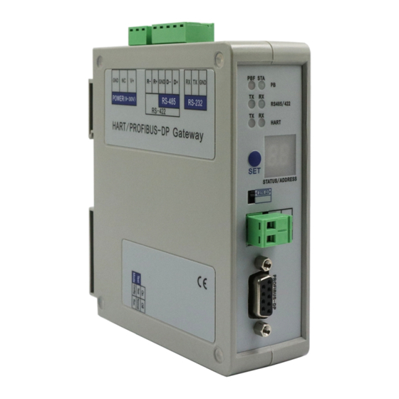
GT200-HT-DP HART to PROFIBUS DP M / ODBUS Gateway User Manual 2 Hardware Descriptions 2.1 Product Appearance RS232 Interface RS485/422 Interface Power Interface Indicators Address Setting Button Resistor Switch HART Interface PROFIBUS Interface Configuration Switch Note: This picture is for reference only. Product appearance should refer to the real object. -
Page 8: Configuration Switch
If the GT200-HT-DP is configured as PROFIBUS DP slave, it has no effects. 2.4 Address Setting Button The address setting button is located on the front panel of the GT200-HT-DP. It’s used to set the PROFIBUS DP/Modbus address (range: 0 to 99). -
Page 9: Resistor Switch
2.5 Resistor Switch The GT200-HT-DP has an internal series resistor (270 Ohm, 2 W) required for the HART channel, that allows up to 13 HART instruments to be connected. When the power of the series resistor is more than 2W, you must use an external series resistor (250 Ohm, 3 W), allowing the gateway to be connected to up to 15 HART instruments. -
Page 10: Rs-485/422 Interface
GT200-HT-DP HART to PROFIBUS DP M / ODBUS Gateway User Manual 2.6.3 RS-485/422 Interface Description R-, RS-422 Receive- R+, RS-422 Receive+ D-, RS-485/422 Transmit- D+, RS-485/422Transmit+ 2.6.4 RS-232 Interface Description RX, connected to user’s device RS-232 TX TX, connected to user’s device RS-232 RX GND, connected to user’s device RS-232 GND... -
Page 11: Topology Of Gt200-Ht-Dp And Hart Instruments
HART to PROFIBUS DP M / ODBUS Gateway User Manual 2.7 Topology of GT200-HT-DP and HART Instruments Notes: It is recommended to use separate power supplies for the HART instruments and the GT200-HT-EI, to ensure stable communication. To improve the communication efficiency of the field bus, it is recommended not to configure an empty node or useless commands in the SST-HT-CFG software. - Page 12 GT200-HT-DP HART to PROFIBUS DP M / ODBUS Gateway User Manual WWW.SSTCOMM.COM...
-
Page 13: Hardware Installation
GT200-HT-DP HART to PROFIBUS DP M / ODBUS Gateway User Manual 3 Hardware Installation 3.1 Machine Dimension Size (width * height * depth): 1.6 in * 5.0 in 4.4 in (40 mm * 125 mm * 110 mm) WWW.SSTCOMM.COM... -
Page 14: Installation Method
GT200-HT-DP HART to PROFIBUS DP M / ODBUS Gateway User Manual 3.2 Installation Method Using 1.38 in (35mm) DIN RAIL. Install the gateway Uninstall the gateway Use a screwdriver to pass through the DIN RAIL bar, pull down and hold. -
Page 15: Quick Start Guide
It is suggested to use the standard PROFIBUS DP connector shown in chapter 2.6.2. If you want the GT200-HT-DP to act as a Modbus slave, connect the Modbus master to the gateway, refer to chapter 2.6.3 or 2.6.4. - Page 16 GT200-HT-DP HART to PROFIBUS DP M / ODBUS Gateway User Manual Click “Field Bus” at left. Configure the parameters to meet the needs of your project. The mode will determine the behavior of the gateway. Click “HartChannel0” at left. Configure the parameters located in the Configuration Section to meet the needs of your project.
- Page 17 GT200-HT-DP HART to PROFIBUS DP M / ODBUS Gateway User Manual Right Click “Node(#)”. Select “Add Command”. In the select Command window, double click the command you wish to add. Note: Command 3 is usually used to read Primary, Secondary, Tertiary, and Quaternary Variables.
- Page 18 HART data to the PROFIBUS DP or Modbus network. 10. Check the mapping address in the Conflict Detection window to confirm that there is no conflict. 11. Click “Download” to download your configurations into the GT200-HT-DP. 12. Turn the configuration switch to “1-OFF 2-OFF” and restart the gateway.
-
Page 19: Configure Profibus Dp Modules
Import the GSD file of GT200-HT-DP. (Download at www.sstcomm.com) Find the GT200-HT-DP device in the catalog. Add a GT200-HT-DP to the PROFIBUS DP bus. Set the same DP address that you have configured for GT200-HT-DP. Add some modules for GT200-HT-DP and set the data address. For more details of PROFIBUS DP module, please see chapter 7. - Page 20 GT200-HT-DP HART to PROFIBUS DP M / ODBUS Gateway User Manual Compile and download the configuration. WWW.SSTCOMM.COM...
-
Page 21: Sst-Ht-Dp Software Instructions
SST-HT-CFG is the configuring software based on the Windows platform, and is used to configure HART series products. The following describes how to use the software, SST-HT-CFG, and configure the GT200-HT-DP. You may also read the software user manual to get more detailed information. - Page 22 GT200-HT-DP HART to PROFIBUS DP M / ODBUS Gateway User Manual New: Create a new configuration file Save: Save the configuration file Open: Open the configuration file AddNode: Add a HART slave node DelNode: Delete a HART slave node AddCmd: Add HART commands...
-
Page 23: Configure Fieldbus
GT200-HT-DP HART to PROFIBUS DP M / ODBUS Gateway User Manual Diagnose: Data monitor. Debug: Send request frames to the HART channel and show the response information from HART channel. 5.3 Configure Fieldbus 5.3.1 Modbus Slave Mode If you want to use the functionality of Modbus slave, click the “Fieldbus” in the tree view, select the mode as “Modbus slave”... -
Page 24: Universal Mode (User Config)
GT200-HT-DP HART to PROFIBUS DP M / ODBUS Gateway User Manual not to clear the HART input data buffer. Timeout number: set the timeout/clear times. 5.3.2 Universal Mode (User Config) The universal mode (transparent transmission mode) means that we can send a HART frame directly through the serial port (RS232/RS485/RS422) while the gateway will also send out the data received from the HART bus through serial port. -
Page 25: Configure Hart Channel
GT200-HT-DP HART to PROFIBUS DP M / ODBUS Gateway User Manual Numbers of input bytes: Setting through the modeling software of PROFIBUS master, it can’t be changed. Numbers of output bytes: Setting by the configuration software of PROFIBUS master, it can’t be changed. -
Page 26: Add Hart Commands
GT200-HT-DP HART to PROFIBUS DP M / ODBUS Gateway User Manual Note: When the configuration node numbers are more than the actual connected devices, The redundant node will lead to the longer times in the polling circle. It is recommended that the configured node numbers should be the same as the other actual devices. -
Page 27: Delete Commands
GT200-HT-DP HART to PROFIBUS DP M / ODBUS Gateway User Manual Change-of-state output: Execute this command once s data buffer of HART changes. Polling output: This order is a put in the polling list, executed periodically. Initialization output: Execute the command only once when power is on. -
Page 28: Delete Nodes
GT200-HT-DP HART to PROFIBUS DP M / ODBUS Gateway User Manual 5.4.5 Delete Nodes Select the node needed to deleted, right click the mouse and click “Delete Node”. Through the menu command you can execute the same action. 5.5 Conflict Detection Users can check the mapping address in the Conflict Detection Window. -
Page 29: Upload Configuration
GT200-HT-DP HART to PROFIBUS DP M / ODBUS Gateway User Manual 5.7 Upload Configuration Click the Upload icon, select the computer port connected to the gateway and then click “Upload Data”. 5.8 Download Configuration Click the Download icon to download the configuration into the gateway. Before downloading the file, please make sure you finish all the configuration. -
Page 30: Diagnose
User Manual channel in the absence of a PROFIBUS or Modbus master station. Steps are as follows: First set the debugging DIP switch to “ON”, then restart the gateway. Now, the GT200-HT-DP is in debugging mode. Connect the RS-232 interface of the gateway and the serial port of the computer with the serial cable and open the software“SST-HT-CFG”, click “Config—serial setting”, Select the correct serial port. - Page 31 / ODBUS Gateway User Manual Ensure that the gateway’s debug switch is in the ON state, and then restart the gateway. The GT200-HT-DP will then be in debugging mode. Connect the RS-232 interface of the gateway and the serial port of the computer with the serial cable., Open the software, “SST-HT-CFG”, Click “Config—serial setting”, Select the correct serial port.
-
Page 32: Serial Debug
GT200-HT-DP HART to PROFIBUS DP M / ODBUS Gateway User Manual Click on “Refresh” to refresh the command status, or “Periodically refresh” to update the data every 500 ms. Double click on a command to open the detailed information. Note: The SST-HT-CFG supports monitoring all HART commands, but detailed information only for command 0, 1, 2, 3, 6, 11, 12, 13, 14, 15, 16, 17, 18 and 19. - Page 33 User Manual the HART channel, concrete operations are as follows: First put the gateway’s debug DIP switch to “ON” state and restart the gateway. Now, GT200-HT-DP is in the debugging mode. Connect the RS232 interface of GT200-HT-DP with the computer and open the software “SST-HT-CFG”. click “Config—serial setting”...
-
Page 34: Data Conversion Tools
GT200-HT-DP HART to PROFIBUS DP M / ODBUS Gateway User Manual In this example, command 0 is composed of a data head, data and check code. It uses a short address. when you click “Send”, you will get the response data. -
Page 35: Working Principle
/ ODBUS Gateway User Manual 6 Working Principle 6.1 Address Table The GT200-HT-DP has a memory buffer of 5000 bytes. From byte 0 to 2999 of the buffer is used for the HART input data and output data. HART Buffer... - Page 36 (1) R (Read): The Modbus master can only use function code 04 to read these data from the GT200-HT-DP. (2) W (Write): The Modbus master can use function code 03 to read these data from the GT200-HT-DP, and use function code 06 or 16 to write data to the GT200-HT-DP.
- Page 37 GT200-HT-DP HART to PROFIBUS DP M / ODBUS Gateway User Manual HART channel status: The present status of the HART channel. Table 6.1 - HART Channel Status Value Description No data communication Sending request Waiting for response Processing response Device N_cmd0 statues: The status of the HART command 0 which is automatically sent. See Note 5 above.
-
Page 38: Flowchart Of Executing One Hart Command
Enable Universal Mode. Disable Universal Mode. 6.2 Flowchart of Executing One HART Command 6.3 Universal Mode The GT200-HT-DP supports two universal mode, which allows users to receive/send original HART data. Set the Mode to “User Config” in the SST-HT-CFG software. WWW.SSTCOMM.COM... -
Page 39: Trigger Command
3x1197 register (Response error counter) will add one. 6.4 Trigger Command When the GT200-HT-DP acts as a Modbus slave, users can trigger any HART command by sending a trigger byte and command index, following the steps below: (The address table refers to chapter 6.1) Disable the polling output. -
Page 40: Data Mapping
0005 3005 For example, in STEP7, add the following modules on the slot of the GT200-HT-DP. The I address corresponds to input buffer data and the Q address corresponds to output buffer. The IB260~323 corresponds to bytes 0000~0063 of GT200-HT-DP input buffer. The IB512~527 of next input module corresponds to bytes 0064~0079. -
Page 41: Profibus Dp Modules
GT200-HT-DP HART to PROFIBUS DP M / ODBUS Gateway User Manual 7 PROFIBUS DP Modules The supported PROFIBUS DP modules are shown below. Module Integrity 4 Words Input, 4 Words Output Word 8 Words Input, 8 Words Output Word 24 Words Input, 24 Words Output... - Page 42 GT200-HT-DP HART to PROFIBUS DP M / ODBUS Gateway User Manual WWW.SSTCOMM.COM...
Need help?
Do you have a question about the GT200-HT-DP and is the answer not in the manual?
Questions and answers