
Related Manuals for SST Automation GT200-EI-CO


Summary of Contents for SST Automation GT200-EI-CO
- Page 1 CANopen / Ethernet Gateway GT200-EI-CO User Manual V 2.4 Rev A SST Automation Email: support@sstautomation.com www.SSTAutomation.com...
- Page 2 The product has many applications. The users must make sure that all operations and results are in accordance with the safety of relevant fields, and the safety includes laws, rules, codes and standards. Copyright Copyright © 2022 by SST Automation. All rights reserved. Trademark is the registered trade mark of SST Automation.
-
Page 3: Table Of Contents
Catalog 1 Product Overview ..............................1 1.1 Product Function ............................1 1.2 Product Features ............................. 1 1.3 Technical Specifications ..........................1 1.4 Related Products .............................3 1.5 Revision History .............................3 2 Hardware Descriptions .............................. 4 2.1 Product Appearance ............................4 2.2 LED Indicators ............................... 5 2.3 DIP Switch ..............................6 2.4 Interface ................................6 2.4.1 Power Interface ........................... -
Page 4: Product Overview
1 Product Overview 1.1 Product Function GT200-EI-CO is a gateway that can provide a seamless connection between CANopen and EtherNet/IP. It can connect CANopen devices to an EtherNet/IP network and realize bi-directional data exchange easily. The gateway converts the devices on the CANopen network to EtherNet/IP network devices. - Page 5 Supports maximum 64 PDO commands and maximum 128 SDO commands. Supports fast Download SDO and fast Upload SDO. The COB-ID of TPDO and RPDO can be set by the user, or the default COBID can be used. ...
-
Page 6: Related Products
1.4 Related Products Related products include: GT100-CO-RS GT200-CO-RS GT200-PN-CO GT200-DP-CO GT100-EI-RS GT200-EI-2RS485 www.sstautomation.com To get more information about related products, please visit SSTCOMM website: 1.5 Revision History Revision Date Chapter Description V2.4, Rev A 8/12/2022 Chapter 1.1, 1.2, 1.3, Revised some mistakes. -
Page 7: Hardware Descriptions
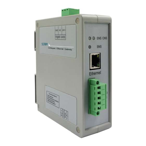
2 Hardware Descriptions 2.1 Product Appearance 24VDC Interface CANopen Status Indicator EtherNet/IP Status Indicator Ethernet Interface CAN Interface DIP Switch Note: This picture is for reference only. The product appearance is subject to the actual product. www.SSTAutomation.com... -
Page 8: Led Indicators
2.2 LED Indicators State State description Green On EtherNet/IP connection established Green Blinking EtherNet/IP connection is not established Indicates an IP address conflict EtherNet/IP connection timed out Red Blinking BOOTP Checking whether the IP address conflicts Orange light Blinking (Blinking alternately Configuration status with the orange light of CNS) -
Page 9: Dip Switch
Configuration mode, with fixed IP address 192.168.0.10, only can read and write configuration data BootLoader mode, with fixed IP address 192.168.0.10 Note: After changing the switch, please restart the GT200-EI-CO to apply the settings. 2.4 Interface 2.4.1 Power Interface 24V+ Function... -
Page 10: Ethernet Interface
2.4.2 Ethernet Interface The Ethernet interface is a RJ-45 socket. Signal description TXD+, Tranceive Data+, Output TXD-, Tranceive Data-, Output RXD+, Receive Data+, Input Bi-directional Data+ Bi-directional Data- RXD-, Receive Data- Bi-directional Data+ Bi-directional Data- www.SSTAutomation.com... -
Page 11: Can Port
2.4.3 CAN Port 5-pin connector: CAN-L CAN-H Shield The gateway uses open five-pin connector at the side of CAN: Connection V+ (Optional) CAN-H Shield (Optional) CAN-L Note: Connections V+, GND, and shield are optional. Only connections CAN-H and CAN-L are required. www.SSTAutomation.com... -
Page 12: Mounting
3 Mounting 3.1 Mechanical Dimensions Size: 1.57 in * 4.92 in * 4.33 in (width * height * depth) 3.2 Mounting Method Use 13.8 in (35 mm) DIN Rail. www.SSTAutomation.com... - Page 13 Install the gateway Uninstall the gateway 1. Use a screwdriver to pass through the DIN RAIL bar, pull down, and hold. 2. Pull out the gateway. 3. Lift up to unload the gateway. ③ ② ① www.SSTAutomation.com...
-
Page 14: Quick Start Guide
4 Quick Start Guide 4.1 Gateway Configuration Make sure the GT200-EI-CO is in the appropriate operating mode that allows for configuration. It is recommended to set the gateway to configuration mode (configuration switches Bit 1 ON and Bit 2 OFF) then the IP of the gateway will be fixed at 192.168.0.10. - Page 15 The default IP of GT200-EI-CO in configuration mode is 192.168.0.10, and users can connect GT200-EI-CO and PC in two ways: 1. Connect the GT200-EI-CO and PC directly with a crossover network cable, as shown below: 2. Connect the GT200-EI-CO, PC and Ethernet router (gateway, Hub, switch) with a straight-through network cable, as shown below: Note: In the configuration mode, the IP address of the PC must be changed to 192.168.0.X;...
-
Page 16: Operation
4.3 Operation 4.3.1 Data Exchange Mode Communication mode between CANopen and EtherNet/IP is asynchronous mode, as shown below: EtherNet/IP “Data 1” shows the data transfer process from EtherNet/IP to CAN; “Data 2” shows the data transfer process from CAN to EtherNet/IP. An EtherNet/IP I/O output can carry 0 to multiple CAN frame data. - Page 17 GT200-EI-CO supports Clear Data Time for TPDO: As long as GT200-EI-CO does not receive the TPDO from the slave within the set time, GT200-EI-CO will clear the data in corresponding position of the EtherNet/IP input buffer. GT200-EI-CO supports simple NMT function: it supports simple startup of all CANopen slave functions.
-
Page 18: Software Instructions
SST-ECO-CFG is configuration software based on the Windows platform, and is used to configure parameters and commands of the product GT200-EI-CO. This manual describes the method of configuring the gateway, GT200-EI-CO. Please read the manual carefully before using it. 5.2 Notes Before Configuration If it is the first time using the product, please set the configuration DIP switch (Bit 1 ON and Bit 2 OFF), and configure the product parameters under configuration mode. -
Page 19: Software Function
5.3 Software Function 5.3.1 User Interface 5.3.2 Toolbar Toolbar is shown as bellow: The function of Toolbar: New, Open, Save, Add Node, Delete Node, Add Command, Delete Command, Upload, Download, Calculate Mapping Address and Export EXCEL. New: Create a new configuration project Save: Save current configuration Open: Open a configuration project www.SSTAutomation.com... -
Page 20: New Configuration Project
Add Node: Add a CANopen node Delete Node: Delete a CANopen node Add Command: Add a CANopen command Delete Command: Delete a CANopen command Upload: Read the configuration information from the module and show it in the software Download: Download the configuration file to the gateway Calculate Mapping Address: Used to automatically calculate the mapped memory address without conflict by each command Export EXCEL: Export current configuration to the local hard disk, saved as .xls file... -
Page 21: Open And Save Configuration
5.3.4 Open and Save Configuration Select "Open", you can open the configuration project that you have saved. Select "Save" or "Save as", you can save the configuration project with .chg as its extension. www.SSTAutomation.com... -
Page 22: Upload And Download
Select "Upload", it will read the configuration applied from the gateway, and the interface is shown as below: Select "Download", it will download the configurations to the gateway, and the interface is shown as below: Note: The IP address is fixed at 192.168.0.10 in GT200-EI-CO configuration mode www.SSTAutomation.com... -
Page 23: Industrial Ethernet Configuration Parameters
IP Address: IP address of GT200-EI-CO. Subnet Mask: Subnet mask of GT200-EI-CO. Default Gateway: Gateway address GT200-EI-CO is located in LAN. VendCode: Users can change VendCode, default is 1. 5.3.7 CANopen Configuration Parameters Configure CANopen network parameters including CANopen Baud Rate, CANopen Node ID, SDO Response Timeout, Enable NMT, Clear Data Time for TPDO, SYNC, Guard Life, The Cycle for RPDO Transmission, Delay to Start up and Control &... -
Page 24: Device View Interface
CANopen configuration interface is shown as below: 5.3.8 Device View Interface 5.3.8.1 Device View Interface 5.3.8.2 Operation Mode Supports three kinds of operation modes: edit menu, edit toolbar, and edit menu by right-click. www.SSTAutomation.com... - Page 25 Edit Menu Edit Toolbar Edit Menu by Right Click 5.3.8.3 Operation Types Add node: Left click on CANopen Networks or existing nodes, and then perform the operation of adding a new node. Then there will be a new node named "New node" under CANopen Network (The newly added node has no address.
- Page 26 Add commands: Left click on the node, and then perform the operation of adding command to add a command for the node. The command selecting dialog box will pop up for users to choose from. Shown as below: Commands: Upload SDO->ENet In, Download SDO <- ENet Out, Transmit PDO-> ENet In, Receive PDO<- ENet Out Select commands: Double click a command.
- Page 27 CANopen Baud Rate: 10K, 20K, 50K, 100K, 125K, 250K, 500K, 1000K can be selected; the default value is 250K. CANopen Node ID: 1 to 127, the default value is 127. SDO Response Timeout: This parameter is based on 10 milliseconds. The range of the parameter value is 1 ...
- Page 28 SYNC: Synchronizing cycle. 0: Do not use synchronizing cycle function. Nonzero value: Use the function. The synchronizing cycle is a nonzero integral multiple of 1 millisecond. The range is 0 to 2000. The default value is 0. Guard Life: Life-guarding function. ...
- Page 29 5.3.8.5 Command Configuration In the device interface, left click on a command and then the configuration interface is shown as below: Slave address: CANopen slave address, the range is 1 to 127. Index value: Object index value in object dictionary (decimal). ...
- Page 30 Mnemonic description: Users can input the description of project configuration items here; these are not actually downloaded to gateway and is mainly used as reference when configuring. Note: Max TPDO commands ≤ 64 Max RPDO commands ≤ 64 Max Upload SDO commands ≤ 128 Max Download SDO commands ≤...
- Page 31 5.3.8.7 View Device Information View the basic information of the currently connected device including device serial number, production date, firmware version number, hardware version number, and IP address. www.SSTAutomation.com...
-
Page 32: Ethernet/Ip Connection Parameters
6 Ethernet/IP Connection Parameters The connection parameters provided by the gateway are as follows: Number Input Instance Output Instance Configuration Instance 112(132Bytes) 111(128Bytes) 113(10Bytes) 122(260Bytes) 121(256Bytes) 123(10Bytes) 132(68Bytes) 131(64Bytes) 133(10Bytes) 142(36Bytes) 141(32Bytes) 143(10Bytes) 152(20Bytes) 151(16Bytes) 153(10Bytes) 162(12Bytes) 161(8Bytes) 163(10Bytes) 172(508Bytes) 171(504Bytes) 173(10Bytes) An example of parameter configuration in RSLogix5000 is as follows:... -
Page 33: How To Read/Write I/O Data
7 How to Read/Write I/O Data The following RSLogix 5000 example will describe how to read/write I/O data. 7.1 Read/Write Data by IO Messaging (Recommend) Right click on EtherNet/IP scanner module, click "New Module", as shown below: In the pop-up dialog box, unfold "+" before "Communications", choose "ETHERNET-MODULE", click "OK", as shown below: www.SSTAutomation.com... - Page 34 Configure relevant information in the pop-up window, as shown below: Set Communication Parameters. Please refer to chapter 6. Set the name. IP address of the SST gateway. In the above picture, the module information needs to be configured includes: Name: Name the added EtherNet/IP adapter module Comm Format: Configure data types.
- Page 35 confirmation, this cannot be changed. If you want to change data types, you can create a new module. IP Address: Set the IP address of the EtherNet/IP adapter module (IP address of GT200-HT-EI, configured by the software SST-HI-CFG) chapter 6 Connection Parameters: Set Connection parameters during communication.
- Page 36 In the picture above, SSTGateway:O.Data [0] ~SSTGateway:O.Data [31] is the corresponding output data address of the SST Gateway module in scanner. Unfold "SSTGateway: I", as shown below: In the above picture, the first 4 bytes of SSTGateway: I. Data [0] are the status bytes. SSTGateway:I.Data [1] ~SSTGateway: I.
-
Page 37: Read/Write Data By Msg
7.2 Read/Write Data by MSG 7.2.1 Read Data Create a new project. Ensure it is in the "Offline" mode. Add two new tags "ReadTag" and "ReadData" under the "Controller Tags" and set the type of "ReadTag" as "MESSAGE" and "ReadData" as "DINT [500]". Right click "ReadTag", select "Configure "ReadTag": www.SSTAutomation.com... - Page 38 In the new pop-up window, some parameters need to be set as below: Message Type: CIP Generic Service Type: Select "Get Attribute Single", now, relevant service code will become "e (Hex)" Class: 4 (Hex) Instance: Please refer to chapter 6 EtherNet/IP Connection Parameters ...
- Page 39 behind the Path, the path format is: EthetNet IP hostname, EtherNet/IP scanner slot No., IP address of EtherNet/IP adapter, after setting the path, click "Apply", "Confirm". As is shown below: In this instance, EtherNet/IP hostname is "Scanner", EtherNet/IP scanner slot No. Is "2", EtherNet/IP adapter is "192.168.0.10".
- Page 40 PLC read-data command This is a simple command which can send a read request, it still needs to add some logic commands to trigger this command in the common program. For more detailed information, please refer to RSLogix5000. Download the program to the PLC and set PLC into the "Online" state. Click "Control Tags"...
-
Page 41: Write Data
7.2.2 Write Data Enter the "Offline" mode, add two new tags "WriteTag" and WriteData" under the "Controller Tags". Define the type of "WriteTag" as "MESSAGE" and "WriteData" as "DINT [500]": www.SSTAutomation.com... - Page 42 Enter the "Monitor Tags" interface. input some data beginning from address WriteData[0] in the "WriteData" tag. There, data will be outputted to SST Gateway. Right click "WriteTag", select "Configure "WriteTag"": www.SSTAutomation.com...
- Page 43 In the new pop-up window, there are variables that need configuration as shown below: Message Type: CIP Generic Service Type: Select "Set Attribute Single", now, relevant Service Code will become "10 (Hex)" Class: 4 (Hex) Instance: Please refer to chapter 6 EtherNet/IP Connection Parameters ...
- Page 44 Choose "Communication" label, input the relevant path of connecting EtherNet/IP adapter in the blank space behind the Path, the path format is: EthetNet IP hostname, EtherNet/IP scanner slot No., IP address of EtherNet/IP adapter, after setting the path, click "Apply", "Confirm". As is shown below: In this instance, EtherNet/IP hostname is "Scanner", EtherNet/IP scanner slot No.
- Page 45 Control", as shown below: PLC read-data command PLC write-data command Download the PLC program to the PLC and set PLC to the "Online" state, the data in the "WriteData" will be outputted to EtherNet/IP adapter (SST Gateway). www.SSTAutomation.com...
Need help?
Do you have a question about the GT200-EI-CO and is the answer not in the manual?
Questions and answers