
Related Manuals for SST Automation GT200-PN-3RS


Summary of Contents for SST Automation GT200-PN-3RS
- Page 1 Universal Serial / PROFINET IO Gateway GT200-PN-3RS User Manual V 1.5 Rev A SST Automation E-mail: SUPPORT@SSTCOMM.COM WWW.SSTCOMM.COM...
- Page 2 The product has many applications. The users must make sure that all operations and results are in accordance with the safety of relevant fields, and the safety includes laws, rules, codes and standards. Copyright Copyright © 2022 by SST Automation. All rights reserved. Trademark is the registered trade mark of SST Automation.
-
Page 3: Table Of Contents
GT200-PN-3RS Universal Serial/PROFINET IO Gateway User Manual Catalog 1 Product Overview................................1 1.1 Product Function..............................1 1.2 Product Features..............................1 1.3 Technical Specification............................1 1.4 Related Products..............................2 1.5 Revision History..............................2 2 Hardware Descriptions..............................3 2.1 Product Appearance...............................3 2.2 Indicators................................4 2.3 Interface.................................4 2.3.1 Power Interface............................4 2.3.2 Serial Ⅰ/Ⅱ.............................. -
Page 4: Product Overview
No complicated programming is required, and connection and communication can be realized in a short time. 1.3 Technical Specification [1] At PROFINET side GT200-PN-3RS is PROFINET slave and acts as Modbus master or Modbus slave at serial side. [2] Supports standard PROFINET I/O protocol. -
Page 5: Related Products
GT200-PN-3RS Universal Serial/PROFINET IO Gateway User Manual Stop bits: 1,2 optional. [7] Modbus master: Function code: 01H, 02H, 03H, 04H, 05H, 06H, 0FH and 10H. Format: RTU and ASCII. Function: Cycle output, forbidden output and change of value output of write command. -
Page 6: Hardware Descriptions
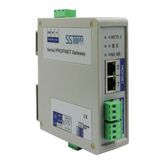
GT200-PN-3RS Universal Serial/PROFINET IO Gateway User Manual 2 Hardware Descriptions 2.1 Product Appearance 24VDC Interface SerialⅠ Indicator SerialⅢ Indicator SerialⅡ Indicator Module Indicator Network Indicator Dual PROFINET Ports SubnetⅠ Subnet Ⅲ SubnetⅡ DIP Switch Note: This picture is for reference only. The product appearance is subject to the actual product. -
Page 7: Indicators
GT200-PN-3RS Universal Serial/PROFINET IO Gateway User Manual 2.2 Indicators Indicators State Description Green blinking Serial port sending data. SerialⅠTX No data is sent. Green blinking Serial port receiving data. SerialⅠRX No data is received. Green blinking/OFF Serial port data/No data is received. -
Page 8: Serial Ⅰ/Ⅱ
GT200-PN-3RS Universal Serial/PROFINET IO Gateway User Manual 2.3.2 Serial Ⅰ/Ⅱ Function D+/TX D+/TX, RS485 Data Positive/RS232 data sending, connect RX of user device D-/RX D-/RX, RS485 Data Negative/RS232 data receiving, connect TX of user device 2.3.3 Serial Ⅲ Function D+, RS485 Data Positive/RS422 Transmit... -
Page 9: Ethernet Interface
Sometimes gateway will appear the phenomenon of configuration failure. At this time, the indicators of the gateway will display: Network indicator NS-OFF, Module indicator MS-Red blinking (the same state as gateway Start-up). And you cannot search GT200-PN-3RS through the configuration software SST-TS-CFG. -
Page 10: Installation
GT200-PN-3RS Universal Serial/PROFINET IO Gateway User Manual 3 Installation 3.1 Machine Dimension Size (width * height * depth): 1.6 in * 5.0 in 4.4 in (40 mm * 125 mm * 110 mm) WWW.SSTCOMM.COM... -
Page 11: Installation Method
GT200-PN-3RS Universal Serial/PROFINET IO Gateway User Manual 3.2 Installation Method Using 1.4 in (35mm) DIN RAIL. Install the gateway Uninstall the gateway 1. Use a screwdriver to pass through the DIN RAIL bar, pull down and hold. 2. Pull out the gateway. -
Page 12: Quick Start Guide
6. Configure the PROFINET network as required. Make sure that the configuration matches the configuration present in the GT200-PN-3RS. When GT200-PN-3RS establishes a connection with the PROFINET master, the gateway will display: NS green on, MS green on. Please note the following three points: The gateway configuration in SST-TS-CFG must be consistent with the settings of configuration software of PROFINET Master station. -
Page 13: Software Instructions
5 Software Instructions 5.1 Software Interface Description SST-TS-CFG is the configuration software based on Windows, and used to configure GT200-PN-3RS through network Interface. Double click software icon ,select GT200-PN-3RS, enter the main interface of software. Remark: In the software, all grey parts cannot be modified. -
Page 14: Device View
Subnet 1,Subnet 2 and Subnet 3 are the same. 5.2.1 Ethernet Configuration View The Ethernet configuration interface is shown as below: In the above parameters, the detailed information is shown as below: IP Address: IP address of GT200-PN-3RS. WWW.SSTCOMM.COM... - Page 15 Subnet Mask: Subnet mask of GT200-PN-3RS. Gateway Address: Gateway address GT200-PN-3RS is located in LAN. Number of Input Bytes: The length of input data needs to be exchanged between GT200-PN-3RS and PLC. It depends on the PROFINET configuration dialog box.
-
Page 16: Subnet Configuration View-Modbus Master
GT200-PN-3RS Universal Serial/PROFINET IO Gateway User Manual 5.2.2 Subnet Configuration View-Modbus Master 1. Modbus Master configuration view The “Modbus Master” configuration interface of “Protocols Select” is shown as below: Baud Rate: 300, 600, 1200, 2400, 4800, 9600, 19200, 38400, 57600 and115200bps optional. - Page 17 GT200-PN-3RS Universal Serial/PROFINET IO Gateway User Manual In Modbus Master and User Config mode (Poll mode of Output mode only), each command has one-bit data to indicate the execution status.The bit is 1 when the command status is normal, otherwise is 0. The length of the status word is 2 bytes.
- Page 18 GT200-PN-3RS Universal Serial/PROFINET IO Gateway User Manual (2) Delete node: Left click on the node to be deleted, and then perform the operation of deleting node. The node and all commands will be deleted. (3) Copy node: Left click on the existing node, choose the node and execute the operation of copying nodes (include all commands under the node).
-
Page 19: Subnet Configuration View-Modbus Slave
GT200-PN-3RS Universal Serial/PROFINET IO Gateway User Manual range: 0~7. Byte Swap: There are four mode of Byte Swap: No swap, Double-byte swap, Four-byte swap and Four-Byte Big-endian and Little-endian Swap. Double-byte swap: The high and low bytes of 2 bytes (one register) are exchanged,e.g., 0x1234 to 0x3412. -
Page 20: Subnet Configuration View-Custom Protocol
GT200-PN-3RS Universal Serial/PROFINET IO Gateway User Manual Transmission Mode: RTU, ASCII. IO Channel Status Word: In Modbus Master and User Config mode (Poll mode of Output mode only), each command has one-bit data to indicate the execution status.The bit is 1 when the command status is normal, otherwise is 0. The length of the status word is 2 bytes. -
Page 21: Subnet Configuration View-User Config
GT200-PN-3RS Universal Serial/PROFINET IO Gateway User Manual In Modbus Master and User Config mode (Poll mode of Output mode only), each command has one-bit data to indicate the execution status.The bit is 1 when the command status is normal, otherwise is 0. The length of the status word is 2 bytes. -
Page 22: Tool
GT200-PN-3RS Universal Serial/PROFINET IO Gateway User Manual Write command (command with data in request). There are three types of output command: Cycle, Forbidden and Change of value. Cycle: Same as Modbus read command (command without data in request) output way. -
Page 23: Upload Config And Download Config
The gateway upload and download via a network cable. After configuration, click “Upload” or “Download” on the tool bar, it will pop up the following interface: If scanning no device, please click “Refresh”. In the above picture, GT200-PN-3RS shows, first select the device and click “Login”. -
Page 24: Conflict Detection
GT200-PN-3RS Universal Serial/PROFINET IO Gateway User Manual Remark: Please confirm the configurations are correct before downloading configurations. If the gateway cannot be searched: Please check whether the computer and gateway are in the same network segment. When using the gateway for ... - Page 25 GT200-PN-3RS Universal Serial/PROFINET IO Gateway User Manual Notes: This function does not support commands in user config mode. (1) Command List Operation It shows configured command in the command list interface. Check box before each command is used to check the position of this command in memory mapping area.
-
Page 26: Export Excel
GT200-PN-3RS Universal Serial/PROFINET IO Gateway User Manual Blue: When address mapping area is located in output area, it will be in blue without conflict. Red: In input area or output area, different command occupied on the same byte, this byte area will be in red. - Page 27 GT200-PN-3RS Universal Serial/PROFINET IO Gateway User Manual Fill in the correct address and data, click the “Write” button. WWW.SSTCOMM.COM...
-
Page 28: Automap
Click “Assign Ethernet Parameters” will pop up below interface: Click “Browse”, the dialog box will be shown as below: You can see that GT200-PN-3RS device is on the LAN, showing its “IP Address”, “MAC Address”, “Device Name”, “Gateway Address” and “Subnet Mask”. - Page 29 Please select the gateway you want to modify and click “Login”.You will see the Ethernet information of the device, for example: “Target MAC Address” : Shows MAC address of GT200-PN-3RS (unmodified). Modify IP Address to “192.168.0.45”, Gateway Address to “192.168.0.45”, Device Name to “test1”and click “OK”, its operation interface is shown as below:...
- Page 30 GT200-PN-3RS devices. If there exits confliction of IP address and device name, users can change IP address and name of GT200-PN-3RS according to chapter “Change IP Info and Name” and ensure that others IP address and name are different (Notes: after changing is complete, some relevant change should be taken in PLC modeling and users must ensure the IP address and name of GT200-PN-3RS is the same with that of PLC modeling).
- Page 31 GT200-PN-3RS Universal Serial/PROFINET IO Gateway User Manual You can see the IP Address is reset to “0.0.0.0”, choose the device and log in, the dialog box is shown as below: Set “IP”, “Subnet” and “Gateway” to “192.168.0.188”, “255.255.255.0” and “192.168.0.1” and you will see the below picture: Click “OK”.
-
Page 32: View Device Information
GT200-PN-3RS Universal Serial/PROFINET IO Gateway User Manual 5.3.7 View Device Information Click “View Device Information”, select the device and click “View”, the device information will be shown as below. WWW.SSTCOMM.COM... -
Page 33: Work Principle
The data conversion between PROFINET network and serial of GT200-PN-3RS is established by "mapping". GT200-PN-3RS has two data buffers, one is input buffer (1K bytes) with address range 0x0000-0x03FF. the other is output buffer (1K bytes) with address range 0x4000-0x43FF. -
Page 34: Custom Protocol
Universal Serial/PROFINET IO Gateway User Manual give any response (if they did), if there exists data in response, GT200-PN-3RS will write them to the address range of 0x0000-0x03FF. The specific data size will depend on users' configuration. 6. User Config-Receiving Only Mode When one serial runs universal mode-receive, it will receive data sent from serial master device and don't give any response. - Page 35 |output data length| output start address| input data length | input start address| 32 output data| parity (accumulated sum) Response frame message: [32] [00 00] [00……00] [92] |input data length| input start address| 50 output data| parity (accumulated sum) | Here the output and input address is memory mapping address of GT200-PN-3RS. WWW.SSTCOMM.COM...
-
Page 36: User Config
6.3 User Config 1. Definition Common mode protocol message of GT200-PN-3RS can be set freely by users, which solves the communication problem between Modbus standard protocol and Modbus nonstandard protocol devices. There are two operation modes under common mode: POLL and READ. Working principle of POLL is similar with Modbus communication protocol, which uses request and response communication way and every subnet can set 30 commands under common mode. - Page 37 GT200-PN-3RS Universal Serial/PROFINET IO Gateway User Manual CRC check L: Message: 01 03 00 00 00 02 C4 0B Response: Slave address: Function code: Number of data: Data: Data: Data: Data: CRC check H: CRC check L: Message: 01 03 04 00 00 00 00 FA 33 Command configuration example is as below: Notes: Under RTU transmission format, supports following parity: None, CRC Check and Sum Check.
- Page 38 GT200-PN-3RS Universal Serial/PROFINET IO Gateway User Manual For example, configuring Modbus command, ASCII transmission format: : (3A) Slave Function Number of data Data 1 …… Data n LRC high byte LRC low byte (0D) (0A) Command configuration example is as below: Notes: Under ASCII transmission format, supports parity: None, LRC Check and Sum Check.
- Page 39 255 bytes. Configuring interface is as below: Communication way: One subnet of GT200-PN-3RS is configured as user config-read and connects to the bar code scanner. another subnet is configured as Modbus slave and connects to the gateway with Modbus master. Modbus master uses 04H function code to read the data beginning from register 0.
Need help?
Do you have a question about the GT200-PN-3RS and is the answer not in the manual?
Questions and answers