
Related Manuals for SST Automation GT200-PN-DM


Summary of Contents for SST Automation GT200-PN-DM
- Page 1 DeviceNet / PROFINET Gateway GT200-PN-DM User Manual V3.2 SST Automation E-mail: support@sstautomation.com www.SSTAutomation.com www.SSTAutomation.com...
- Page 2 Important Information Warning The data and examples in this manual cannot be copied without authorization. SST Automation reserves the right to upgrade the product without notifying users. The product has many applications. The users must make sure that all operations and results are in accordance with the safety of relevant fields, and the safety includes laws, rules, codes and standards.
-
Page 3: Table Of Contents
4 Instructions .....................................12 4.1 Quick Start Guide ............................... 12 4.1.1 Pre-operation Mode-Scanning and debugging adapter devices in DeviceNet network ........12 4.1.2 Operation Mode-Upload or Download Configuration to GT200-PN-DM ............. 18 4.1.3 Operation Mode .............................. 21 4.2 SST-DNET-COM Software Instructions ........................22 4.2.1 Note before configuration .......................... -
Page 4: Product Overview
1 Product Overview 1.1 Product Function GT200-PN-DM is a gateway which can connect device with DeviceNet interface to the PROFINET network. It acts as a device station on the PROFINET side and a scanner on the DeviceNet side. 1.2 Product Features Wide application: Supports connecting multiple DeviceNet devices to the PROFINET network. - Page 5 Operation Mode Support DeviceNet baud rate: 125K, 250K, 500K. PROFINET master ( Siemens S7-300 / 400/ 1200/ 1500 PLCs, etc. ) Support communication with One DeviceNet adapter supports maximum input: 128 bytes, output: 112 bytes. Support connect up to 63 adapter devices, supporting a maximum input/output of 1440 bytes. ...
- Page 6 Output 256 bytes Output 512 bytes Input / Output 001 byte Input / Output 002 bytes Input / Output 004 bytes Input / Output 008bytes Input / Output 016 bytes Input / Output 032 bytes ...
-
Page 7: Hardware Descriptions
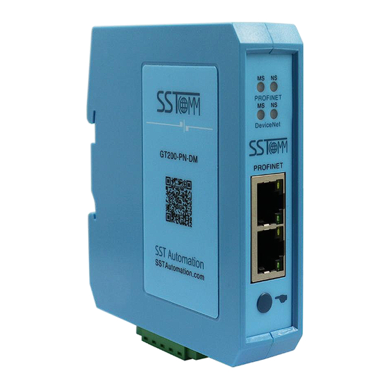
2 Hardware Descriptions 2.1 Product Appearance PROFINET Indicators DeviceNet Indicators PROFINET Interface Configuration Button DeviceNet Interface Notes: This picture is for reference only. The product appearance is subject to the actual product. www.SSTAutomation.com... -
Page 8: Indicators
2.2 Indicators 1. PROFINET LED Indicators Description Always Red Module is running and initialization has not yet completed. Always Green Red blinking(1Hz) Initialization completed, no connection with PLC Red blinking(2Hz) Physical connection in IRT mode does not match the configuration Always Green Always Red No plug-in network cable... -
Page 9: Communication Interface
Press and hold the button Enter bootloader Mode Restart the gateway before powering on 2.4 Communication Interface 2.4.1 DeviceNet Interface GT200-PN-DM supplies power through DeviceNet port, DeviceNet and power terminal, as shown below: Wiring GND(Power GND) CAN_L SHIELD CAN_H... -
Page 10: Ethernet Interface
2.4.2 Ethernet Interface The Ethernet interface uses RJ45 interface, follows the IEEE802.3u 100BASE-T standard. Its pin (standard Ethernet signal) is defined as below: Signal description TXD+ TXD- RXD+ RXD- S4,5,7,8 Reserved www.SSTAutomation.com... -
Page 11: Hardware Installation
3 Hardware Installation 3.1 Mechanical Dimensions Size (width * height * depth): 1.0 in * 4.0 in * 3.6 in (25 mm * 100 mm * 90 mm) 3.2 Installation Method Using 1.4 in (35mm) DIN RAIL. www.SSTAutomation.com... -
Page 12: Instructions
Applicable scene: When the I/O parameters of the adapter in the DeviceNet network are uncertain. Connect GT200-PN-DM and PC via cable, then power on the gateway. Wait until 4 lights on the gateway are on. Press and hold the button for 3 seconds, release the button when MS and NS indicators on the DeviceNet side flash orange once, indicating switching to operating mode. - Page 13 3. Click "Search" and "Search Device" window will pop up. The software will automatically scan the GT200-PN-DM devices on the network and select the gateway that need to be configured (if the device is not scanned, please click refresh to try again), and then Click "Sign In".
- Page 14 Scanner baud rate are settable items. Scanner address refers to the node address of GT200-PN-DM on the DeviceNet bus, and Scanner baud rate refers to the baud rate used by the DeviceNet network. After setting, click "OK".
- Page 15 7. Double-click the adapter station to view the I/O parameters of one of the adapter stations, as shown below: 8. Double-click the scanner icon (node 0 in this example), and the "Property" window will pop up. Click "Scan List", move the available devices from the left to the right scan list, double-click to edit the I/O parameters, set the byte length to read the adapter I/O parameters, and then click OK.
- Page 16 and output data in "Output". The corresponding DeviceNet network parameters can be set in "DeviceNet Parameter Settings". (For detailed usage, please check Chapter 4.3 SST-DNET-COM configuration software) www.SSTAutomation.com...
- Page 17 www.SSTAutomation.com...
-
Page 18: Operation Mode-Upload Or Download Configuration To Gt200-Pn-Dm
9. Click "Apply" to download the parameters into GT200-PN-DM. At this time, the prompt window "Download Successful" will pop up. Click "OK" to return to the main interface. 10. About debugging, if debugging is not required, please skip this process. If debugging is required, double-click the adapter icon (node 1 in this example). - Page 19 “GT200-PN-DM”, or right-click "Upload" in the blank space of the configuration interface and select “GT200-PN-DM”. “Upload” is used to view the configuration saved in GT200-PN-DM. Click "Download" to download the configuration into GT200-PN-DM. www.SSTAutomation.com...
- Page 20 2. If modify the name and IP address on the PROFINET side, click “Network” in the toolbar, select “Assign”, click “Browse” in the pop-up window to select the gateway and click "Sign In". As shown in the figure below, now we can modify the IP address and device name , click “OK”...
-
Page 21: Operation Mode
2. Use a network cable, connect GT200-PN-DM to the PLC.(please download the configuration to the PLC) 3. Connect GT200-PN-DM to the DeviceNet network 4. Power on the GT200-PN-DM. At this time, the GT200-PN-DM will establish communication with the adapter in the DeviceNet network. -
Page 22: Sst-Dnet-Com Software Instructions
4.2.1 Note before configuration Power on the GT200-PN-DM, untill 4 lights of the gateway are on, press and hold the button for 3 seconds, on DeviceNet side MS and NS will orange flash once and then release. The gateway switches to operation mode, and now we can use SST-DNET-COM software to Configurate I/O parameters for adapter devices on the network. - Page 23 You can access SST-DNET-COM software after entering correct activation code. Title Bar Menu Bar Toolbar Configuration Window Tree View Comment Interface Configuration Window: After establishing the internet connection, display the online device and modify the address and parameters of the device online,check the input and output data. In the offline state, you can view device properties by dragging the device icon to the window.
-
Page 24: Toolbar
4.3 Toolbar Toolbar is shown as below: Functions separately from left to right are: New, Open, Save, Print, Cut, Copy, Paste, Refresh viewport, EDS Wizard, Find devices in the device library, find next, Internet Connection, One-Click Save, Disconnect, Send Explicit Message, Property, Device Management, Output. - Page 25 EDS Wizard interface is shown in the following figure: Select "Start "and pop up the following interface: www.SSTAutomation.com...
- Page 26 In this interface, users can choose to register an EDS file, log out of an existing device, and change the icon of a device. Take "Register an EDS file" as an example to introduce the following steps for registering a new EDS file: After selecting "Register an EDS file", click "Next Step"...
- Page 27 Click "Next Step" to pop up the EDS file test report interface. If there is an error in the EDS file, the error message will be displayed in the interface, and there is no "Next Step" operation. If there is no error in the file, continue the "Next Step"...
- Page 28 After selecting a device icon, click "Next Step" to pop up the factory information of the registered device, as shown in the figure below: www.SSTAutomation.com...
- Page 29 SST-DNET-COM software needs to be used together with the DeviceNet scanner module. First, connect GT200-PN-DM to Ethernet, and then connect GT200-PN-DM's DeviceNet port and user's DeviceNet device to the DeviceNet network. Power Supply of GT200-PN-DM is 24VDC. Power on After correctly Connecting to Power Supply, untill 4 lights of the gateway are on, press and hold the button for 3 seconds, on DeviceNet side MS and NS will orange flash once and then release.
- Page 30 Then click the “Search”, the software will display the searched device in the list, select the scanner station to be configured for the interface setting: www.SSTAutomation.com...
-
Page 31: Devicenet Network Scanning
Note: In the interface settings configuration, "IP address" is the IP of the device selected at the time of search. "Scanner Address" is the Address of DeviceNet Scanner Module. Set any value between 0 and 63, which can't conflict with other node addresses on the bus. "Scanner Baud Rate" is the baud rate of DeviceNet scanner module, and has 125K, 250K, and 500K options. -
Page 32: Equipment Parameter Modification And I/O Data Test
"Device ID" displays the information of the device manufacturer, type, device, sort and version. If you choose to configure GT200-PN-DM, after setting all the parameters, you can click the "Apply" button to download. - Page 33 In the "Scan List" option interface, users can select devices to add to the "Scan List" of the scanner and set its I/O parameters: www.SSTAutomation.com...
- Page 34 Add adapter station 2 to the scanner station mapping list, and then select adapter station 2 in the "Scan List". After www.SSTAutomation.com...
- Page 35 selecting it, click "Edit I / O parameters". This interface sets the number of input and output bytes of the adapter: In the "Input", and "Output" options interface, the user can map the address of the device added to the scanner and select automatic mapping.
- Page 36 If users need to map manually, they can also click the "Advanced" button to set the starting address in the dialog box shown below. In the advanced Settings interface, the user can also set the byte exchange mode of this adapter device.There are three types of byte exchange: no-exchange, two-byte exchange, and four-byte exchange.
- Page 37 If you need to set the unit that maps the starting address in "Advanced", click the "Options" button to set it. As shown in the figure below, "Byte Alignment" means in one byte and "Word Alignment" means in two bytes: The settings of the PROFINET side input/output data blocks are set in master station configuration software such as TIA Portal or STEP 7.
-
Page 38: Devicenet Adapter Module Property Introduction
Status word: When Enable, you can monitor the connection status of DeviceNet devices. After Disable, 8 bytes are reserved at the front of the PROFINET input buffer. Each bit of the 8 bytes represents the status of a adapter station. Bit0 of byte 0 represents DeviceNet adapter station No. - Page 39 ID” shows the information of the device manufacturer, type, device, sort and version. (2) Parameter In the “Parameter” interface, the user can upload and download the parameters of the device to facilitate online modification of the device parameter values. www.SSTAutomation.com...
- Page 40 Reset: The “Reset” button can restore the default value of the parameters, and can only “Reset” for a single parameter. Upload: The “Upload” button supports single and full parameter operation. After clicking “Upload”, the interface will display the actual parameter value of the current online adapter DeviceNet device. Download: The “Download”...
- Page 41 The number of bytes in/out of SST-DNET-COM software can also provide this information. In the figure above, the input and Output 64-Bytes bytes provided under the “Polled” project are the default input and output data byte lengths. The maximum number of input bytes supported by SST-DNET-COM software is 128, and the maximum number of output bytes is 112.
- Page 42 If the output data length is incorrect, it will be displayed: Note that after the address is changed in the general interface, because the device with the modified address will be restarted and the DeviceNet internet connection has been disconnected. At this time, the I/O data input and output operation will not be able to see the data.
-
Page 43: Sst-Dnet-Com Software Offline Configuration
Select “GT100-PN-DM/GT200-PN-DM/GT200-DP-DM” from the left and drag it to the bus on the right, Select GT200-PN-DM and double-click the gateway icon to modify the DeviceNet address of the gateway. similarly, drag the DeviceNet adapter device to the bus on the right and modify the DeviceNet device address to be consistent with the actual one, as shown in the following figure: www.SSTAutomation.com... - Page 44 www.SSTAutomation.com...
- Page 45 Double-click the GT200-PN-DM gateway icon, click “Scan List” in the properties interface, select the DeviceNet device to the scan list side on the available devices side, click “Edit I/O Parameters”, and set the actual I/O data length of the device. As shown below:...
- Page 46 www.SSTAutomation.com...
- Page 47 After configuring the DeviceNet device I/O data length, click the input and output interface to map the data. Select the device and click “Map (M)” to map the input/output data, as shown in the following figure: In the “DeviceNet Parameters” setting interface, users can set DeviceNet parameters. “Input Data Hold/Clear” www.SSTAutomation.com...
- Page 48 indicates whether the corresponding DeviceNet input data is cleared when the “number of Command Resennds” errors reaches the set value. Select “Clear” to clear the DeviceNet input data. Select “Hold” to keep the DeviceNet input data as the last correct data received. “Number of Command Resends” indicates the number of times the command is resent when the DeviceNet command response error occurs.
-
Page 49: Send The Explicit Message
4.9 Send the Explicit Message Through explicit message modification, it is the advanced function of DeviceNet network. Users need to have a better understanding of DeviceNet network. After the device is online, click the right button to “send an explicit message”. The interface pops up as shown in the figure above. -
Page 50: Working Principle
The data conversion between GT200-PN-DM's DeviceNet and PROFINET is established through a “ mapping ” relationship. There are two data buffers in GT200-PN-DM, one is PROFINET network input buffer, and the other is PROFINET network output buffer. The DeviceNet read command writes the read data to the network input buffer for PROFINET network reading.
Need help?
Do you have a question about the GT200-PN-DM and is the answer not in the manual?
Questions and answers