
Related Manuals for SST Automation GT200-HT-EI


Summary of Contents for SST Automation GT200-HT-EI
- Page 1 HART / EtherNet/IP Gateway GT200-HT-EI User Manual V 1.3 SST Automation E-mail: SUPPORT@SSTCOMM.COM WWW.SSTCOMM.COM...
-
Page 2: Copyright
The product has many applications. The users must make sure that all operations and results are in accordance with the safety of relevant fields, and the safety includes laws, rules, codes and standards. Copyright Copyright © 2021 by SST Automation. All rights reserved. Trademark is the registered trade mark of SST Automation. -
Page 3: Table Of Contents
2.5 Internal Series Resistor Switch........................4 2.6 Interface................................5 2.6.1 Power Interface............................ 5 2.6.2 Ethernet Interface..........................5 2.6.3 HART Interface............................5 2.7 Topology of GT200-HT-EI and HART Instruments..................6 3 Hardware Installation..............................8 3.1 Machine Dimension............................8 3.2 Installation Method............................8 4 Quick Start Guide..............................9 4.1 Connection.............................. - Page 4 GT200-HT-EI HART/EtherNet/IP Gateway User Manual 5.2.9 Debug Assistant..........................30 5.2.10 Slave Scan............................31 5.2.11 Conversion Tools..........................33 6 Working Principle..............................34 6.1 Data Exchange.............................. 34 6.2 Flowchart of Executing One HART Command................... 35 7 EtherNet/IP Connection Parameters........................36 8 How to Read/Write I/O Data........................... 37 8.1 Read/Write Data by IO Messaging (Recommend)..................37...
-
Page 5: Product Overview
1 Product Overview 1.1 Product Function GT200-HT-EI is a gateway that can provide a seamless connection between HART and EtherNet/IP. It can connect HART slave devices to EtherNet/IP network and realize bi-directional data exchange easily. The HART side can be configured as a primary or secondary master, and the EtherNet / IP side works as a slave. -
Page 6: Important Information
GT200-HT-EI HART/EtherNet/IP Gateway User Manual gateway internal resistor and support connecting 15 HART slaves with an external resistor (250 Ohm). [9] Supports all commands of the HART protocol. [10] Each HART command can be configured for change-of-state output, polling output, initialization output or disable output. -
Page 7: Hardware Descriptions
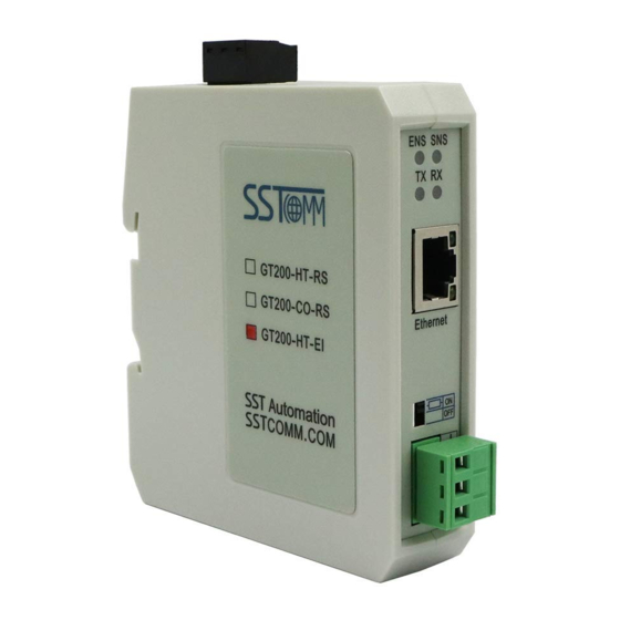
GT200-HT-EI HART/EtherNet/IP Gateway User Manual 2 Hardware Descriptions 2.1 Product Appearance Power Interface configuration Switch Button Ethernet Indicators HART Indicators Ethernet Interface Resistor Switch HART Interface Note: The pictures are for reference only. The product appearance is subject to the actual product. -
Page 8: Button
2.5 Internal Series Resistor Switch The GT200-HT-EI has an internal series resistor (270 Ohm /2 W) required for HART channel, supporting up to 13 HART instruments to be connected. When the power of the series resistor is more than 2W, you must use an external series resistor (250 Ohm /3 W), supporting up to 15 HART instruments to be connected. -
Page 9: Interface
GT200-HT-EI HART/EtherNet/IP Gateway User Manual 2.6 Interface 2.6.1 Power Interface Description Power GND NC (Not Connected) 24V+, DC 24V+ 2.6.2 Ethernet Interface Ethernet interface is a RJ-45 connector, 10/100M adaptive. Description TXD+, Tranceive Data+, Output TXD-, Tranceive Data-, Output RXD+, Receive Data+, Input... -
Page 10: Topology Of Gt200-Ht-Ei And Hart Instruments
GT200-HT-EI HART/EtherNet/IP Gateway User Manual 2.7 Topology of GT200-HT-EI and HART Instruments WWW.SSTCOMM.COM... - Page 11 Notes: It is recommended to use the separate power supply for the HART instruments and the GT200-HT-EI, to ensure the stable communication. To improve the communication efficiency of field bus, it is recommended not to configure the empty node in SST-HI-CFG software or useless commands.
-
Page 12: Hardware Installation
GT200-HT-EI HART/EtherNet/IP Gateway User Manual 3 Hardware Installation 3.1 Machine Dimension Size (width * height * depth): 1.6 in * 5.0 in * 4.4 in / 40mm * 125mm * 110mm 3.2 Installation Method Using 1.38 in (35mm) DIN RAIL. -
Page 13: Quick Start Guide
Select the gateway and click “Sign In” to upload the configuration. Note: Make sure that the GT200-HT-EI and your computer are in the same network segment. If you can’t discovery any gateways, please test the network connection first, referring to the note How to Use the Ping WWW.SSTCOMM.COM... - Page 14 User Manual Command. For the first time to use GT200-HT-EI, the uploaded configuration is a default configuration created by SST Automation. You can change the parameters based on the default configuration or create a new project. The following steps introduce how to configure for a new project.
- Page 15 01 has no request with 12-byte response, the command 03 has no request with 24-byte response, and the command 06 has 1-byte request with 1-byte response. The request data of GT200-HT-EI includes extra 2-byte status, so the receiving data length is 2-byte more than the actual response.
- Page 16 “Download” on the toolbar, select the gateway you want to download to and click “Sign In”. Note: The GT200-HT-EI will apply the new configuration after reset. After downloading, the software will ask to reset the GT200-HT-EI. You can also power off then power on the GT200-HT-EI to reset. Test the communication.
-
Page 17: Test Communication
4.1.2. The SST-HI-CFG software provides debug and monitor tools (chapter5.2.7, 5.2.8, 5.2.9). For more EtherNet/IP connection details, refer to chapter 7 and chapter 8. Set the configuration switched to Bit 1 ON and Bit 2 OFF (debug mode). Restart the GT200-HT-EI to apply the mode switching. - Page 18 HART/EtherNet/IP Gateway User Manual After confirming the data in diagnose window, click “Memory” on the toolbar and sign in the GT200-HT-EI. Check the data bytes and mapping address. The input data in the Memory data window corresponds to the input at EtherNet/IP side. The output data corresponds to the output at EtherNet/IP side.
-
Page 19: Software Instructions
SST-HI-CFG is configuring software based on Windows platform, and used to configure HART series products. The following describes how to use the software SST-HI-CFG to configure the product GT200-HT-EI. You may also check the software user manual to get detailed usage. - Page 20 GT200-HT-EI HART/EtherNet/IP Gateway User Manual New: Create a new configuration file Save: Save the configuration file Open: Open the configuration file AddNode: Add a HART slave node DelNode: Delete a HART slave node AddCmd: Add a HART command DelCmd: Delete a HART command...
-
Page 21: Software Function Description
Configurable items include: Assign IP Mode, IP Address, Subnet Mask, and Gateway Address. Assign IP Mode: Manual Assign, DHCP IP Address: Set the IP address of the device Subnet Mask: Set the subnet mask of GT200-HT-EI.Gateway Address: Set the gateway address of the device WWW.SSTCOMM.COM... -
Page 22: Configure The Hart Fieldbus
GT200-HT-EI HART/EtherNet/IP Gateway User Manual 5.2.2 Configure the HART Fieldbus 5.2.2.1 Set the Parameters of HART Channel Click the HartChannel0 in the tree view and the configuration section will appear on the right: HART Master: Primary master, Secondary master HART Networks: Select the networks mode as single or multiple points, under the single point the gateway can... - Page 23 GT200-HT-EI HART/EtherNet/IP Gateway User Manual 5.2.2.2 Add a Node Select the”HartChannel0”, Right click the mouse and select "Add Node" in the pop-up menu. Click the added node, set slave address in the right configuration plate, and please notice that HART channel can only be equipped with one slave node which address is 0 when configured in the single point mode.
- Page 24 GT200-HT-EI HART/EtherNet/IP Gateway User Manual Note: the same command can only be configured once in one node. 5.2.2.4 Configure HART Commands Click the command number in the tree view. you will see the configuration plate in the right place: Configuration Mode: basic and advanced optional, “basic” is shown as above, “advanced” configuration can refer to chapter 4.2.3.7...
- Page 25 GT200-HT-EI HART/EtherNet/IP Gateway User Manual Mode of outputting command: You can use the execution way of the command, change-of-state, polling output, Initialization output and disable output optional Change-of-state output: Execute this command once s data buffer of HART changes Polling output: This order is put in the polling list, executed periodically...
- Page 26 GT200-HT-EI HART/EtherNet/IP Gateway User Manual 5.2.2.6 Delete Nodes Select the node needed to be deleted, Right click the mouse and click “Delete Node”. Through the menu command can also be the same action. 5.2.2.7 Advanced Options to Configure HART Commands When using HART command configuration, sometimes users want to get one part data of one command.
-
Page 27: Conflict Detection
First to explain the “Mapped Address”: Bytes: response bytes of “Response Data” Memory Address: assigned memory address which this byte is located in memory buffer area of GT200-HT-EI EtherNet/IP register address: the relevant EtherNet/IP register address of “Memory Address”. Note: this address is not a single address, which is the same memory area which it occupied Choose “Byte0-3”... -
Page 28: Auto Mapping
GT200-HT-EI HART/EtherNet/IP Gateway User Manual The left side of the tree view is configuration commands, the right side of the tree view is data memory address including receive data storage address and send data storage. Upper side is memory distribution of the HART’s sending data. -
Page 29: Upload Configuration
GT200-HT-EI HART/EtherNet/IP Gateway User Manual 5.2.5 Upload Configuration Open the software “SST-HI-CFG”, Click on upload icon , Select the gateway what you used in the pop-up dialog box, and click “OK” and then “upload data”, if it shows “upload successfully”, which indicates that configuration file has been uploaded to the SST-HI-CFG. -
Page 30: Download Configuration
EtherNet/IP side. Steps are as follows: Ensure that the GT200-HT-EI’s function bit of configuration switch is in the ON state and the mode bit of configuration switch is in the OFF state, restart the gateway. GT200-HT-EI is in the debug mode. -
Page 31: Diagnose
1. Ensure that the GT200-HT-EI’s function bit of configuration switch is in the ON state and the mode bit of configuration switch is in the OFF state, restart the gateway. GT200-HT-EI is in the debug mode. - Page 32 GT200-HT-EI HART/EtherNet/IP Gateway User Manual Click on “HartChannel0” in this interface, it will show the status of HART fieldbus part in the right place, press “Refresh” button will update the data once, click on “Periodically refresh”, the software will update the data every 500ms.
- Page 33 GT200-HT-EI HART/EtherNet/IP Gateway User Manual It shows the response status of configured commands. Click “Refresh” will fresh these command status, “Periodically refresh” will fresh command status once. Double click command 0, 3, 6 will show their command information, command 03 can start data input.
-
Page 34: Debug Assistant
HART. Steps are as follows: 1. Ensure that the GT200-HT-EI’s function bit of configuration switch is in the ON state and the mode bit of configuration switch is in the OFF state, restart the gateway. Now GT200-HT-EI is in the debug mode. -
Page 35: Slave Scan
The slave scan function can help users to check the HART slave address and modify the slave address. The operation steps are: Dial the configuration switch of GT200-HT-EI to 1ON2OFF to let the gateway into debug mode. Use a network line to connect GT200-HT-EI to computer, open SST-HI-CFG software, click “Tool->Slave Scan”... - Page 36 GT200-HT-EI HART/EtherNet/IP Gateway User Manual Click “Start” in “Slave Scan” interface, it will show the short address, long address and ID of HART slave devices which are connecting gateway. Move to the relevant device and right click it, and click “Modify slave address” will show “Modify slave address”...
-
Page 37: Conversion Tools
GT200-HT-EI HART/EtherNet/IP Gateway User Manual After modification, it means HART slave address has been modified, restart the gateway. 5.2.11 Conversion Tools In the “Tools” menu, there are two practical tools: They are used to switch between IEEE754 and PACKED ASCII conveniently. -
Page 38: Working Principle
Data exchange between HART and EtherNet/IP via GT200-HT-EI is established on “mapping”. There are two data buffer areas in the GT200-HT-EI: One is EtherNet/IP network input buffer and the other is EtherNet/IP network output buffer. The received data from HART instruments will be mapped to the input buffer for EtherNet/IP scanner reading. -
Page 39: Flowchart Of Executing One Hart Command
GT200-HT-EI HART/EtherNet/IP Gateway User Manual 6.2 Flowchart of Executing One HART Command WWW.SSTCOMM.COM... -
Page 40: Ethernet/Ip Connection Parameters
GT200-HT-EI HART/EtherNet/IP Gateway User Manual 7 EtherNet/IP Connection Parameters Connection parameters the adapter provides are as below: Data Size 64 Bytes 128 Bytes 256 Bytes Parameters Input Instance Output Instance Configuration Instance Notes: The Input data size should include 4-byte status. For example, when using the 256-byte parameters, the input size should be 260 bytes. -
Page 41: How To Read/Write I/O Data
GT200-HT-EI HART/EtherNet/IP Gateway User Manual 8 How to Read/Write I/O Data The following RSLogix 5000 example will describe how to read/write I/O data. 8.1 Read/Write Data by IO Messaging (Recommend) Right click on EtherNet/IP scanner module, click "New Module", as shown below: In the pop-up dialog box, unfold "+"... - Page 42 GT200-HT-EI HART/EtherNet/IP Gateway User Manual Configure relevant information in the pop-up window, as shown below: Set Communication Parameters. Please refer to chapter 7. Set the name. IP address of the SST gateway. In the above picture, the module information needs to be configured includes: Name: Name the added EtherNet/IP adapter module Comm Format: Configure data types.
- Page 43 User Manual confirmation, this cannot be changed. If you want to change data types, you can create new module IP Address: Set IP address of the EtherNet/IP adapter module (IP address of GT200-HT-EI, configured by the software SST-HI-CFG) Connection Parameters: Set Connection parameters during communication. Please refer to chapter 7 Note: "Size"...
- Page 44 GT200-HT-EI HART/EtherNet/IP Gateway User Manual In the above picture, SSTGateway:O.Data [0] ~SSTGateway:O.Data [31] is the corresponding output data address of SST Gateway module in scanner. Unfold "SSTGateway: I", as shown below: In the above picture, the first 4 bytes of SSTGateway: I. Data [0] are the status bytes. SSTGateway:I.Data [1] ~SSTGateway: I.
-
Page 45: Read/Write Data By Msg
GT200-HT-EI HART/EtherNet/IP Gateway User Manual 8.2 Read/Write Data by MSG 8.2.1 Read Data Create a new project. it is in the "Offline" mode. Add two new tags "ReadTag" and "ReadData" under the "Controller Tags" and set the type of "ReadTag" as "MESSAGE" and "ReadData" as "DINT [500]". - Page 46 GT200-HT-EI HART/EtherNet/IP Gateway User Manual In the new pop-up window, it needs to set some parameters as below: Message Type: CIP Generic Service Type: Select "Get Attribute Single", now, relevant service code will become "e (Hex)" Class: 4 (Hex) ...
- Page 47 GT200-HT-EI HART/EtherNet/IP Gateway User Manual behind the Path, the path format is: EthetNet IP hostname, EtherNet/IP scanner slot No., IP address of EtherNet/IP adapter, after setting the path, click "Apply", "Confirm". As is shown below: In this instance, EtherNet/IP hostname is "Scanner", EtherNet/IP scanner slot No. Is "2", EtherNet/IP adapter is "192.168.0.10".
- Page 48 GT200-HT-EI HART/EtherNet/IP Gateway User Manual PLC read-data command This is a simple command which can sent a read request, it still needs to add some logic commands to trigger this command in common program. About the detailed information, please refer to RSLogix5000.
-
Page 49: Write Data
GT200-HT-EI HART/EtherNet/IP Gateway User Manual 8.2.2 Write Data Enter the "Offline" mode, add two new tags "WriteTag" and WriteData" under the "Controller Tags". Define the type of "WriteTag" as "MESSAGE" and "WriteData" as "DINT [500]": WWW.SSTCOMM.COM... - Page 50 GT200-HT-EI HART/EtherNet/IP Gateway User Manual Enter the "Monitor Tags" interface. input some data beginning from address WriteData[0] in the "WriteData" tag. There data will be outputted to SST Gateway. Right click "WriteTag", select "Configure "WriteTag"": WWW.SSTCOMM.COM...
- Page 51 GT200-HT-EI HART/EtherNet/IP Gateway User Manual In the new pop-up window, it needs to configure as below: Message Type: CIP Generic Service Type: Select "Set Attribute Single", now, relevant Service Code will become "10 (Hex)" Class: 4 (Hex) ...
- Page 52 GT200-HT-EI HART/EtherNet/IP Gateway User Manual Choose "Communication" label, input the relevant path of connecting EtherNet/IP adapter in the blank space behind the Path, the path format is: EthetNet IP hostname, EtherNet/IP scanner slot No., IP address of EtherNet/IP adapter, after setting the path, click "Apply", "Confirm". As is shown below: In this instance, EtherNet/IP hostname is "Scanner", EtherNet/IP scanner slot No.
- Page 53 GT200-HT-EI HART/EtherNet/IP Gateway User Manual Control", as shown below: PLC read-data command PLC write-data command Download PLC program to the PLC and set PLC to "Online" state, the data in "WriteData" will be outputted to EtherNet/IP adapter (SST Gateway). WWW.SSTCOMM.COM...
Need help?
Do you have a question about the GT200-HT-EI and is the answer not in the manual?
Questions and answers