
Related Manuals for SST Automation GT200-DN-RS


Summary of Contents for SST Automation GT200-DN-RS
- Page 1 Modbus/DeviceNet Gateway GT200-DN-RS User Manual REV 1.4 SST Automation E-mail: SUPPORT@SSTCOMM.COM WWW.SSTCOMM.COM...
-
Page 2: Table Of Contents
GT200-DN-RS Modbus/DeviceNet Gateway User Manual Catalog 1 About This Document..............................4 1.1 General................................4 1.2 Important User Information..........................4 1.3 Terms................................4 2 Product Overview..............................5 2.1 Product Function.............................5 2.2 Product Features............................. 5 2.3 Technical Specification...........................5 2.4 Attention................................7 2.5 Related Products............................. 7 3 Product Appearance.............................. - Page 3 GT200-DN-RS Modbus/DeviceNet Gateway User Manual 5.5 Conflict Detection............................25 5.5.1 Operation of Command List......................26 5.5.2 Operation of Memory Mapping Area....................26 5.6 Hardware Communication..........................27 5.6.1 Serial Configuration.......................... 27 5.6.2 Upload Configuration........................28 5.6.3 Download Configuration........................28 5.7 Load and Save Configuration........................29 5.7.1 Load Configuration Project.......................
-
Page 4: About This Document
User Manual 1 About This Document 1.1 General This document describes every parameter of the gateway GT200-DN-RS and provides using methods and some announcements that help users use the gateway. Please read this document carefully before using the gateway. For further information, documentation etc., please visit the SSTCOMM website: http://www.sstcomm.com. -
Page 5: Product Overview
Modbus network, and a slave at the side of DeviceNet network. It supports RS-485 and RS-232 at the serial interface. Comparing with other products, GT200-DN-RS adds the debugging function, which makes the application so convenient in industrial field. RS-485 interface is used for communication while RS-232 interface is used to debug, and RS-232 interface is used for communication while RS-485 interface is used to debug. - Page 6 GT200-DN-RS Modbus/DeviceNet Gateway User Manual Trunk lines Thick cable and thin cable both can be used to build the trunk lines. When the thick cable and thin cable are mixed to build the trunk lines, the longest cable length can be calculated through the following formulas:...
-
Page 7: Attention
GT200-DN-RS Modbus/DeviceNet Gateway User Manual 2.4 Attention To prevent stress, prevent module panel damage; To prevent bump, module may damage internal components; Power supply voltage control in the prospectus, within the scope of the requirements to burn module;... -
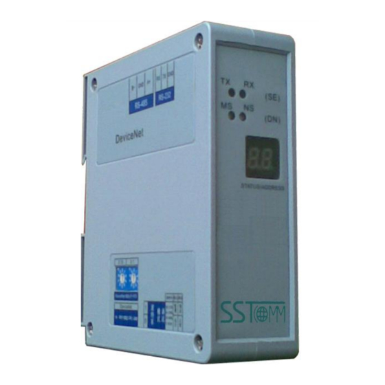
Page 8: Product Appearance
GT200-DN-RS Modbus/DeviceNet Gateway User Manual 3 Product Appearance RS-485 Indicators Interface RS-232 Interface DeviceNet address Setting switches of baud rate and working modes DeviceNet interface Note: This picture is only for reference, the product appearance should take the material object as a standard. -
Page 9: Status Setting Switches And Led
2) Set working mode: Configuration and run mode are optional. At the status of configuration, the LED shows “CF”. 3) Set debugging: Debug and normal mode are optional. GT200-DN-RS has the function of debugging, and it provides users with easy way for debugging Modbus network data communications. At the status of debugging, the LED shows “db”. -
Page 10: Setting Switches Of Devicenet Address
Debug 01:250K 10:500K Normal 11: Automatic Note: If you reset the status switches, you should restart GT200-DN-RS (power off and power on) to make the settings take effect. 3.2.2 Setting Switches of DeviceNet Address ×10 ×1 According to the above, the DeviceNet address is calculated as follow: DeviceNet address = (A ×... -
Page 11: Communication Interface
GT200-DN-RS Modbus/DeviceNet Gateway User Manual 3.3 Communication Interface 3.3.1 Modbus Interface Modbus interface use open 3 pin pluggable terminal, users could accord to the panel instruction to wire: Function B-, RS-485 A+, RS-485 RS-485 interface Function RX, connect to RX of user’s device RS-232 TX, connect to TX of user’s device RS-232... -
Page 12: Devicenet Interface
GT200-DN-RS Modbus/DeviceNet Gateway User Manual 3.3.2 DeviceNet Interface 5-pin connector: -24V CAN- CAN+ +24V Shielding Open 5-pin connector at the side of DeviceNet: Wiring GND(24V) CAN- shielding CAN+ +24V WWW.SSTCOMM.COM... -
Page 13: Use Method
GT200-DN-RS Modbus/DeviceNet Gateway User Manual 4 Use Method 4.1 Quick Start Guide 1. Setting DeviceNet address manually Before connecting DeviceNet master, sets DeviceNet address by moving code switch at the gateway’s side. The range of DeviceNet effective address is 0 to 63. The calculation method of DeviceNet address is shown at chapter 3.2.2 of the document. -
Page 14: Hardware Wiring
The data exchange between GT200-DN-RS Modbus and DeviceNet is established by “mapping”. GT200-DN-RS has two data buffers, one is DeviceNet network input buffer, and the other is DeviceNet network output buffer. Modbus read commands read the data and then write the data into input buffer for DeviceNet network reading. -
Page 15: Terminal Resistor
GT200-DN-RS will send writing-commands, and transmit data to Modbus slave devices. If AB’s PLC is in programming mode, there will be no the network output-data. Note 3: During the configuration of GT200-DN-RS, when polling mode of output commands is set to ... -
Page 16: Software Instructions
5.1 Notes before Configuration SST-MD-CFG is software which bases on Windows platform, and used to configure the gateway GT200-DN-RS.. Users could set Modbus and fieldbus parameters and commands. This document introduces the using method of GT200-DN-RS. After installed, double-click on the icon and enter into Configuration interface. - Page 17 GT200-DN-RS Modbus/DeviceNet Gateway User Manual Toolbar: Toolbar is shown as below: The function of Toolbar: New, Open, Save, Add Node, Delete Node, Add Command, Delete Command, Upload, Download, Conflict Detection, Auto Mapping, Export EXCEL and Monitor I/O Data.. New: Create a new configuration project...
-
Page 18: Device View Operation
GT200-DN-RS Modbus/DeviceNet Gateway User Manual Upload: Read the configuration information from the module and shown in the software Download: Download the configuration file to the gateway Conflict Detection: To check whether there are some conflicts with configured commands in the gateway... -
Page 19: Operation Types
3) Add command operation: Right-click on the node, and then you can add a command for the node. The commands dialog box is shown as follow: Currently, GT200-DN-RS supports the commands: 01, 02, 03, 04, 05, 06, 15 and 16 commands Select the command: Double click on the command... -
Page 20: Configuration View Operation
GT200-DN-RS Modbus/DeviceNet Gateway User Manual 4) Delete command operation: Right-click on the command and then you can delete command. 5) Rename nodes: Left-click on the node to be renamed, and then the edit status will be shown and you can rename it. -
Page 21: Interface Of Subnet Configuration
GT200-DN-RS Modbus/DeviceNet Gateway User Manual 5.4.2 Interface of Subnet Configuration The protocol type is Modbus Master, and configurable parameters are shown as follows: Modbus communication baud rate, data bits, check bit, Stop bits, transmission mode, response timeout, delay between polls, output mode, scan rate and communication interface. - Page 22 GT200-DN-RS Modbus/DeviceNet Gateway User Manual Baud Rate: There are 300, 600, 1200, 2400, 9600, 19200, 38400, 57600 and 115200bps to be selected. Data Bits: 8 bits Check Bit: There are none, odd, even, mark and space to be selected. Stop Bits: There are 1 and 2 to be selected.
-
Page 23: Interface Of Node Configuration
GT200-DN-RS Modbus/DeviceNet Gateway User Manual Scan Rate: Scan Rate is the ratio of fast scan cycle to slow scan cycle. If this parameter value is set to 10 then every fast scan command will be sent 10 times and those slow scan commands will be sent once. - Page 24 GT200-DN-RS Modbus/DeviceNet Gateway User Manual Starting Address: the starting address of the register/switching value/coil in Modbus salve device, the range of the parameter value is 0 to 65535. Number of Data: The number of register/switching value/coil of Modbus slave. Mapping address (HEX): The starting address of data in memory buffer of the module...
-
Page 25: Comment Interface
GT200-DN-RS Modbus/DeviceNet Gateway User Manual express a four-byte value, they can use "four-byte swap", maybe it will achieve. Type of Scan: There are two ways, fast scan and slow scan. Every Modbus command can be set to fast scan or slow scan. The gateway will send Modbus command according to the "Scan Rate". Slow scan is fast scan multiples scan rate. -
Page 26: Operation Of Command List
GT200-DN-RS Modbus/DeviceNet Gateway User Manual 5.5.1 Operation of Command List All the configuration commands can be shown at the command list. Each select box before command is used for checking the memory-mapping location of the command. Click on the command can select the check box, and in the memory-mapping area it can show the corresponding share of spatial location. -
Page 27: Hardware Communication
GT200-DN-RS Modbus/DeviceNet Gateway User Manual Click on the input or output grid, whether the grid is occupied or not is shown as follows: 5.6 Hardware Communication Hardware communications' menu items are shown as follow: 5.6.1 Serial Configuration The software automatically scan the available serial port of system, and the available serial can be shown in serial list. -
Page 28: Upload Configuration
GT200-DN-RS Modbus/DeviceNet Gateway User Manual 5.6.2 Upload Configuration Choose upload configuration, upload the configuration from gateway to the software, the interface is shown as follows: Note: Before uploading the configuration, please check whether the port is the available port. 5.6.3 Download Configuration... -
Page 29: Load And Save Configuration
GT200-DN-RS Modbus/DeviceNet Gateway User Manual Note1: Before downloading the configuration, please check whether the port is the available port. Note 2: Before downloading the configuration, make sure that all configurations has been completed. 5.7 Load and Save Configuration 5.7.1 Load Configuration Project Select "Open", you can open the configuration project that you have saved. -
Page 30: Export Excel File
GT200-DN-RS Modbus/DeviceNet Gateway User Manual 5.8 Export Excel File Excel document helps users to examine the configuration related. Choose the icon , save the configuration as excel document and choose the right path. Double-click to open the document, and it divided to three parts: "Command List", "Fieldbus", and "Subnet". -
Page 31: Monitor I/O Data
GT200-DN-RS Modbus/DeviceNet Gateway User Manual 5.9 Monitor I/O Data The function is for debugging Modbus network communications, the interface is shown as follows: Memory mapping address: Starting address of data writing into the gateway memory Data: Data writing into the gateway When Modbus slave has no response or response timeout: WWW.SSTCOMM.COM... - Page 32 GT200-DN-RS Modbus/DeviceNet Gateway User Manual When Modbus responses are right: After filling the "Memory mapping address" and "Data" rightly, users can click on "Transmit" button to transmit the packet. User clicks on the "Save content" button can save the received data to a computer's hard disk.
- Page 33 GT200-DN-RS Modbus/DeviceNet Gateway User Manual WWW.SSTCOMM.COM...
-
Page 34: Installation
GT200-DN-RS Modbus/DeviceNet Gateway User Manual 6 Installation 6.1 Machine Dimension Size: 1.57 in (width)*4.92 in (height)*4.33 in (depth) 6.2 Installation 35mm DIN rail installation WWW.SSTCOMM.COM... - Page 35 GT200-DN-RS Modbus/DeviceNet Gateway User Manual WWW.SSTCOMM.COM...
-
Page 36: Instructions Of Devicenet I/O And Parameters
GT200-DN-RS Modbus/DeviceNet Gateway User Manual 7 Instructions of DeviceNet I/O and parameters 7.1 I/O Configuration DeviceNet input-bytes could be configured as 8 bytes, 16 bytes, 32 bytes, 64 bytes, 96 bytes, 128 bytes or 160 bytes. DeviceNet output-bytes could be configured as 8 bytes, 16 bytes, 32 bytes, 64 bytes, 96 bytes and 112 bytes. -
Page 37: Devicenet Network Configuration Instructions
7.3 DeviceNet Network Configuration Instructions Users need to install the *.EDS file in the disc to DeviceNet configuration software, then you can configure GT200-DN-RS through network configuration software. EDS (Electronic Data Sheet) is comprehensive description which supports DeviceNet network function. It equals to equipment's driver of Windows. - Page 38 GT200-DN-RS Modbus/DeviceNet Gateway User Manual WWW.SSTCOMM.COM...
- Page 39 Step4: Register gateway GT200-DN-RS Shown as above, select “Register an EDS file”, as follow: Please register GT200-DN-RS.EDS file we provided, according to the place where you save EDS file, and select the file. Step 5: Confirm register file you choose...
- Page 40 GT200-DN-RS Modbus/DeviceNet Gateway User Manual Click “Next” : Step 6: Select the icon. Following network configuration software will prompt you the equipment category in equipment storehouse, you may choose icon in this process. WWW.SSTCOMM.COM...
- Page 41 GT200-DN-RS Modbus/DeviceNet Gateway User Manual Here, the device has successfully registered to the icon library location of configuration software's equipment storehouse. WWW.SSTCOMM.COM...
- Page 42 Modbus/DeviceNet Gateway User Manual Registration location of gateway EDS Then, you should connect gateway GT200-DN-RS to DeviceNet network, click on “SCAN” button of RsNetWorx, or select “Network-Online” in menu bar, your gateway will be scanned by system and identified exactly. WWW.SSTCOMM.COM...
Need help?
Do you have a question about the GT200-DN-RS and is the answer not in the manual?
Questions and answers