
Related Manuals for SST Automation GT200-DPM-EI


Summary of Contents for SST Automation GT200-DPM-EI
- Page 1 PROFIBUS DP / EtherNet/IP Gateway GT200-DPM-EI User Manual V 1.4 SST Automation Email: support@sstautomation.com www.SSTAutomation.com...
- Page 2 SST Automation shall not be responsible or liable for misuse of the information contained herein.
-
Page 3: Table Of Contents
Table of Contents 1 Product Overview ..............................1 1.1 Product Function ............................1 1.2 Product Feature ...............................1 1.3 Technical Specifications ..........................1 1.4 Revision History .............................2 2 Hardware Descriptions .............................. 3 2.1 Product Appearance ............................3 2.2 Indicators ................................ 4 2.3 Interfaces ................................ 4 2.3.1 Ethernet Interface .......................... - Page 4 8.1 EtherNet/IP Communication Parameters ..................... 33 8.2 Read/Write Data by IO Messaging (Recommend) ..................34 8.3 Read/Write Data by MSG ..........................38 8.3.1 Read Data ............................38 8.3.2 Write Data ............................42 www.SSTAutomation.com...
-
Page 5: Product Overview
1 Product Overview 1.1 Product Function The GT200-DPM-EI gateway can connect PROFIBUS DP devices to EtherNet/IP network, and implement data communication between EtherNet/IP and PROFIBUS DP. It acts as a PROFIBUS DP master and a EtherNet/IP adapter. 1.2 Product Feature Wide Application: Implement the connection between the PROFIBUS DP devices and the EtherNet/IP ... -
Page 6: Revision History
[10] Installation: 1.38in (35mm) DIN Rail. [11] Protection level: IP20. 1.4 Revision History Revision Date Chapter Description V1.4 5/8/2024 New release V1.3 7/15/2021 New release V1.1 8/17/2017 New release www.SSTAutomation.com... -
Page 7: Hardware Descriptions
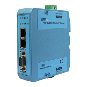
2 Hardware Descriptions 2.1 Product Appearance Configuration Switch Power Interface Indicators Ethernet interface PROFIBUS DP Interface RS232 Interface Mini USB B Interface Notes: This picture is for reference only. The product appearance is subject to the actual product. www.SSTAutomation.com... -
Page 8: Indicators
2.2 Indicators Indicator State Description Green PROFIBUS DP communication is normal Green blinking More than one DP master are in the same network At least one DP slave is disconnected No DP configuration or no IP address assigned in DHCP mode Green DP master initialized normally Green, blinking irregularly... -
Page 9: Profibus Dp Interface
2.3.2 PROFIBUS DP Interface PROFIBUS DP wiring instructions as shown below: GND (Pin 5) PROFI_A (Pin 8) PROFI_B (Pin 3) Signal Description Not connected Not connected Data P (B), must be connected PROFI_B Request to send Isolated ground for +5VDC PROFI_5V Isolated +5VDC Not connected... -
Page 10: Configuration Switch
2.3.5 Configuration Switch Description Function (Bit 1) Mode (Bit 2) Run mode, allow set the IP address of the gateway Configuration mode (fixed IP address 192.168.0.10) Run mode,forbidden to set the IP address spare 2.3.6 Power Interface 24V+ Description Ground Not connected +24V DC www.SSTAutomation.com... -
Page 11: Hardware Installation
3 Hardware Installation 3.1 Mechanical Dimensions Size (width * height * depth):1.4 in * 4.6 in * 4.3 in (34mm * 116mm * 107.4mm) 3.2 Mounting Method Use 13.8 in (35 mm) DIN Rail. www.SSTAutomation.com... - Page 12 www.SSTAutomation.com...
-
Page 13: Quick Start Guide
Ethernet cable. (2) Configure the PROFIBUS DP parameters, referring to chapter 8. Download the configuration by the USB cable or RS-232 cable. Connect the GT200-DPM-EI with the PROFIBUS DP devices and an EtherNet/IP scanner, then test the data transformation. www.SSTAutomation.com... -
Page 14: Working Principle
By creating the data conversion between the EtherNet/IP and PROFIBUS DP through mapping, there are two data buffers in the GT200-DPM-EI. The gateway will write the data from the PROFIBUS DP devices to the network input buffer, then output to the corresponding EtherNet/IP Scanner by POLL I/O write command. -
Page 15: Configure Ethernet Parameters
6 Configure Ethernet Parameters 6.1 SST-EPM-CFG Software Instructions SST-EPM-CFG is a configuration software to configure GT200-DPM-EI parameters, based on Windows OS. Supported OS: WinXP, Win7, Win8, Win10. 6.2 Software Interface Description The main interface is as shown below: Title Bar... -
Page 16: Function Descriptions
Notes: All gray parts are non-configurable items. Assign IP Mode: Manual Assign, DHCP optional. IP Address: Set the IP address of the GT200-DPM-EI. Subnet Mask: Set the subnet mask of the GT200-DPM-EI. Default Gateway:Set the IP address of default gateway. -
Page 17: Upload Configuration
Vendor Code: Can be modified according to needs, the input range is: 1-65535. The default value is 1. Keep Alive Sending Rate: After the gateway sends Keep Alive and receives a correct reply, the rate that it sends the next packet of Keep Alive. The default is 8, unit: second. The range: 1-60000. Keep Alive Retry Interval: The time interval to send the next packet of Keep Alive after it does not receive a correct reply when sending a Keep Alive. -
Page 18: Download Configuration
6.3.3 Download Configuration Select Download Configuration to download the configured gateway information to the gateway device. The download and upload steps are similar: Notes: Before downloading, please confirm all the configuration data is correct. Select device, click Sign In. Then click Download. After the download is completed, it will prompt whether to perform a reset operation. -
Page 19: Loading Configuration Project
6.3.5 Loading configuration project Select "Open" to open the saved .chg file. 6.3.6 Excel Export Select "Export Excel" in the Tool menu, or click the icon on the Toolbar, to export the configuration to an Excel Table. www.SSTAutomation.com... -
Page 20: Configure Profibus Dp Parameters
7 Configure PROFIBUS DP Parameters 7.1 Install SYCON.net The STCON.net setup application is in the Configuration Tools folder (downloaded at www.sstcomm.com). 1. Open the folder “SYCON.net” and run the “SYCONnet netX setup”. 2. Select the language. 3. Install the application following the instructions: www.SSTAutomation.com... - Page 21 4. Set the User Name and Organization. www.SSTAutomation.com...
- Page 22 5. Select a setup type. If you select the Custom Setup, you can set the Installation path and the features to install. It’s recommended to install all the features. www.SSTAutomation.com...
- Page 23 6. Click Install to begin the installation and wait for installing. www.SSTAutomation.com...
-
Page 24: Start To Configure
7.2 Start to Configure 1. Open the SYCON.net. For the first time to open the software, it requires to set the password. If you don’t want to set the password, please leave blank and click OK. The second time and thereafter to open the software, if you didn’t set the password before, please directly click OK to enter the configuration window. - Page 25 2. Save the project first. www.SSTAutomation.com...
-
Page 26: Configure Dp Master Parameters
3. Open the Field device folder “Profibus DP V0” >> “Master” at right. Select “COMX DP/DPM” device, left-click on it and drag one onto the gray bus line at left, as shown below: 7.3 Configure DP Master Parameters Double click on the master module and enter “Configuration” windows. Configure the parameters and apply the changes. -
Page 27: Add Profibus Dp Devices
7.4 Add PROFIBUS DP Devices 1. Import the GSD files: (1) Select “Network” >> “Import Device Descriptions...” in the top menu. (2) Select the a GSD file of your device to import. Follow the instructions to finish importing. www.SSTAutomation.com... - Page 28 (3) The device modules are in Vendor folders at right. 2. Select the device, left-click on it and drag it onto the red bus line of the master module at left. You can add many devices onto the red bus line. www.SSTAutomation.com...
-
Page 29: Configure Devices Parameters
7.4.1 Configure Devices Parameters 1. Double click on a device and configure the parameters. Please refer to the appropriate documentations. For example, (1) In the “Configuration” >> “Modules” window, insert some modules as the configured modules. www.SSTAutomation.com... - Page 30 (2) In the “Configuration” >> “Parameters” window, configure the common parameters and module parameters. Select the Module and Display mode at the top of the window. Notes: Some devices don’t supports configure the parameters by master configuration tools. www.SSTAutomation.com...
-
Page 31: Set The Station Address
2. Apply the changes and click OK. 7.4.2 Set the Station Address Double click on the master module “COMX...” and open the configuration window. In “Configuration” >> “Station Table” window, set the DP station address and apply the changes. www.SSTAutomation.com... -
Page 32: Download The Configuration
Before downloading the configuration to the GT200-DPM-EI, please confirm the configured parameters are correct. 1. Connect the GT200-DPM-EI with the computer by the Mini USB cable or RS-232 cable. Please refer to chapter 2.3.3 for details. 2. Double click on the master module “COMX...” and enter “Settings” >> “Driver” window. Tick the two driver and apply the changes, as shown below: www.SSTAutomation.com... - Page 33 3. Enter “Settings” >> “Driver” >> “netX Driver” window, enable the USB/RS232 connector and select the correct COM port. The COM port can be confirmed in the Windows Device Manager. Save and apply the changes. www.SSTAutomation.com...
- Page 34 4. Enter “Settings” >> “Device Assignment” window, scan the suitable devices and tick the correct device, then apply the connection, as shown below: www.SSTAutomation.com...
- Page 35 5. Close the configuration window. Right click on the master module “COMX...” and select Connect. If the connection is successful, the name of the module will turn green. 6. When connecting successfully, right click on the master module “COMX...” and select Download. www.SSTAutomation.com...
- Page 36 Click Yes to continue and wait for downloading. www.SSTAutomation.com...
-
Page 37: Communication With Ethernet/Ip Scanner
8 Communication with EtherNet/IP Scanner 8.1 EtherNet/IP Communication Parameters Connection parameters the adapter provides are as below: Data Size 260 Bytes 492 Bytes Parameters Input Instance Output Instance Configuration Instance Notes: The Input data size should include 4-byte status. For example, when using the 260-byte parameters, the input size should be 264 bytes. -
Page 38: Read/Write Data By Io Messaging (Recommend)
8.2 Read/Write Data by IO Messaging (Recommend) Right click on EtherNet/IP scanner module, click "New Module", as shown below: In the pop-up dialog box, unfold "+" before "Communications", choose "ETHERNET-MODULE", click "OK", as shown below: www.SSTAutomation.com... - Page 39 Configure relevant information in the pop-up window, as shown below: Set Communication Parameters. Please refer to chapter 9.1. Set the name. IP address of the SST gateway. In the above picture, the module information needs to be configured includes: Name: Name the added EtherNet/IP adapter module. www.SSTAutomation.com...
- Page 40 Comm Format: Configure data types. Users can choose data types as DINT, INT, SINT and REAL, etc. After confirmation, this cannot be changed. If you want to change data types, you can create new module. IP Address: Set IP address of the EtherNet/IP adapter module (IP address of GT200-DPM-EI, configured by the software SST-EPM-CFG).
- Page 41 SST Gateway module in scanner. Unfold "SSTGateway: I", as shown below: In the above picture, the first 4 bytes of SSTGateway: I. Data [0] are the status bytes. SSTGateway:I.Data [1] ~SSTGateway: I. Data [32] are the input data from GT200-DPM-EI. www.SSTAutomation.com...
-
Page 42: Read/Write Data By Msg
8.3 Read/Write Data by MSG 8.3.1 Read Data Create a new project; it is in the "Offline" mode. Add two new tags "ReadTag" and "ReadData" under the "Controller Tags" and set the type of "ReadTag" as "MESSAGE" and "ReadData" as "DINT [500]". Right click "ReadTag", select "Configure "ReadTag": www.SSTAutomation.com... - Page 43 In the new pop-up window, it needs to set some parameters as below: Message Type: CIP Generic Service Type: Select "Get Attribute Single", now, relevant service code will become "e (Hex)" Class: 4 (Hex) Instance: Please refer to chapter 9.1 EtherNet/IP Connection Parameters. Attribute: 3 (Hex) Destination: Select "ReadData"...
- Page 44 behind the Path, the path format is: EthetNet IP hostname, EtherNet/IP scanner slot No., IP address of EtherNet/IP adapter, after setting the path, click "Apply", "Confirm". As is shown below: In this instance, EtherNet/IP hostname is "Scanner", EtherNet/IP scanner slot No. Is "2", EtherNet/IP adapter (SST Gateway) is "192.168.0.10".
- Page 45 PLC read-data command This is a simple command which can sent a read request, it still needs to add some logic commands to trigger this command in common program. About the detailed information, please refer to RSLogix5000. Download the program to the PLC and set PLC into "Online" state. Click "Control Tags"...
-
Page 46: Write Data
8.3.2 Write Data Enter the "Offline" mode, add two new tags "WriteTag" and WriteData" under the "Controller Tags". Define the type of "WriteTag" as "MESSAGE" and "WriteData" as "DINT [500]": www.SSTAutomation.com... - Page 47 Enter the "Monitor Tags" interface; input some data beginning from address WriteData[0] in the "WriteData" tag. There data will be outputted to SST Gateway. Right click "WriteTag", select "Configure "WriteTag"": www.SSTAutomation.com...
- Page 48 In the new pop-up window, it needs to configure as below: Message Type: CIP Generic Service Type: Select "Set Attribute Single", now, relevant Service Code will become "10 (Hex)" Class: 4 (Hex) Instance: Please refer to chapter 9.1 EtherNet/IP Connection Parameters. Attribute: 3 (Hex) Source Element: Select "WriteData"...
- Page 49 Choose "Communication" label, input the relevant path of connecting EtherNet/IP adapter in the blank space behind the Path, the path format is: EthetNet IP hostname, EtherNet/IP scanner slot No., IP address of EtherNet/IP adapter, after setting the path, click "Apply", "Confirm". As is shown below: In this instance, EtherNet/IP hostname is "Scanner", EtherNet/IP scanner slot No.
- Page 50 Control", as shown below: PLC read-data command PLC write-data command Download PLC program to the PLC and set PLC to "Online" state, the data in "WriteData" will be outputted to EtherNet/IP adapter (SST Gateway). www.SSTAutomation.com...
Need help?
Do you have a question about the GT200-DPM-EI and is the answer not in the manual?
Questions and answers