
Related Manuals for SST Automation GT200-DP-RS


Summary of Contents for SST Automation GT200-DP-RS
- Page 1 Universal Serial/PROFIBUS DP Gateway GT200-DP-RS User Manual V6.1 SST Automation E-mail: SUPPORT@SSTCOMM.COM WWW.SSTCOMM.COM...
-
Page 2: Table Of Contents
GT200-DP-RS Universal Serial/PROFIBUS DP Gateway User Manual Catalog 1 About the Gateway..................................4 1.1 Product Function................................4 1.2 Product Features................................4 1.3 Technical Specifications..............................4 1.4 Related Products................................6 2 Quick Start Guide..................................7 2.1 Power Wiring.................................. 7 2.2 Wiring with PC................................7 2.3 Configuration Method.............................. - Page 3 GT200-DP-RS Universal Serial/PROFIBUS DP Gateway User Manual 6.4.3 Interface of Node Configuration View......................34 6.4.4 Interface of Command Configuration View......................35 6.4.5 Notes View.................................37 6.5 Conflict Detection.................................38 6.5.1 Operation of Command List..........................39 6.5.2 Operation of Memory Mapping Area........................40 6.6 Hardware Communication............................41 6.6.1 Serial Configuration............................41 6.6.2 Upload Configuration............................42...
-
Page 4: About The Gateway
1.1 Product Function The gateway GT200-DP-RS enables data to establish communication between the serial port and PROFIBUS DP (PROFIBUS DP master such as Siemens PLC). At the same time it can remotely obtain real-time I / O data, status and other information of the connected PLC and serial device via docking cloud platforms such as bokaiyun to achieve remote monitoring. - Page 5 GT200-DP-RS Universal Serial/PROFIBUS DP Gateway User Manual 3. As a Modbus master, it supports 01H, 02H, 03H, 04H, 05H, 06H, 0FH and 10H function codes. Use configuration software to configure: It can be configured up to 100 Modbus commands. 03H and 04H support "Word / Byte mapping". Through the high-byte or low-byte mapping of the registers can effectively utilize PROFIBUS DP input-byte;...
-
Page 6: Related Products
GT200-DP-RS Universal Serial/PROFIBUS DP Gateway User Manual 1.4 Related Products Other related products in SSTCOMM: GT100-DP-RS and so on. If you want to get more information about these products, please visit SSTCOMM website: http://www.sstcomm.com. WWW.SSTCOMM.COM... -
Page 7: Quick Start Guide
2.2 Wiring with PC Establish the connection the RS-232 interface of gateway with PC, the wiring method is shown as follow: 2.3 Configuration Method GT200-DP-RS V6.1 version product supports two methods to configure: One is through configuration software, the WWW.SSTCOMM.COM... - Page 8 DP hardware configuration (this method is new added function of V6.X). It also supports USB and RS232 interface to configure. The LED Display of GT200-DP-RS will show in DP slave address and “-U” or “-P” alternately. When showing “-U” on LED Display, the gateway is in the “Software configuration” state; When showing “-P”, it means the gateway is in “DP Hardware Configuration”...
-
Page 9: Wiring With Serial Device
GT200-DP-RS Universal Serial/PROFIBUS DP Gateway User Manual 2.4 Wiring with Serial Device After finishing configuration, wire communication interface, the wiring method of RS-232 is the same with "wiring with PC", the wiring method of RS-485 is shown as follow: The wiring method of RS-422 is shown as follow:... -
Page 10: Wiring Profibus Dp Interface
When RS-485 is in the communication of point to multi-point, to prevent the reflection and obstruction of signal, users need to use two terminal resistances in furthest ports of line, and the parameters are 120Ω 1/2W. Note: There is no terminal resistor inside RS-485 interface of GT200-DP-RS. 2.5 Wiring PROFIBUS DP Interface Suggest wiring PROFIBUS DP with standard PROFIBUS DP connector. -
Page 11: Debug
2.6 Debug GT200-DP-RS supports three operating modes: Modbus Master, Modbus Slave and User Config. GT200-DP-RS supports debugging function in three modes. Quickly press the button for 3 times, GT200-DP-RS enter into debug mode, the LED display shows “db” always on. -
Page 12: Hardware Descriptions
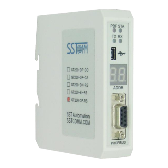
GT200-DP-RS Universal Serial/PROFIBUS DP Gateway User Manual 3 Hardware Descriptions 3.1 Product Appearance Power Interface Indicators USB Interface Button LED Display PROFIBUS DP Interface RS-232 Interface RS-485/RS-422 Interface Note: This picture is for reference only. Product appearance should accord to the real object. -
Page 13: Indicators
GT200-DP-RS Universal Serial/PROFIBUS DP Gateway User Manual 3.2 Indicators Indicators State Description Always Red PROFIBUS DP communication fails. Close Communication is ok. Green Blinking PROFIBUS DP is communicating. Close PROFIBUS DP is not communicating. Green Blinking RS-485/422 port is sending data. -
Page 14: Profibus Dp Address Setting Button
1) Under normal working condition of the GT200-DP-RS, digital tube always displays the address of the current PROFIBUS DP address. Quickly press (double-click) the button twice in succession, the high bit starts flash, and the low bit always on, click the button to add 1 to start setting the PROFIBUS DP address high bit. -
Page 15: Interface
GT200-DP-RS Universal Serial/PROFIBUS DP Gateway User Manual 3.4 Interface 3.4.1 Power Interface 24V+ Function NC(No Connect) 24V+, DC plus 24V 3.4.2 PROFIBUS DP Interface GND (Pin 5) PROFI_A (Pin 8) PROFI_B (Pin 3) WWW.SSTCOMM.COM... -
Page 16: Rs-485/Rs-422 Interface
The maximum output current of pin 5 and pin6 is 80mA. 3.4.3 RS-485/RS-422 Interface The RS-485 interface of GT200-DP-RS is standard, and the RS-485 characteristics of the product are shown as follows: 1. -
Page 17: Rs-232 Interface
GT200-DP-RS Universal Serial/PROFIBUS DP Gateway User Manual Function R-, RS-422 Receive Negative R+, RS-422 Receive Positive D-, RS-485/RS-422 Transmit Negative D+, RS-485/RS-422Transmit Positive 3.4.4 RS-232 Interface RS-232 interface uses a 3-pin pluggable open terminal, and its pin description is shown as follows:... -
Page 18: Working Principle
The data conversion between Modbus of GT200-DP-RS Modbus Slave and PROFIBUS is established by mapping relation. GT200-DP-RS has two data buffers, one is PROFIBUS network input buffer, and the other is PROFIBUS network output buffer. Network input and output buffers are relative to PROFIBUS. Modbus write-register commands write data... - Page 19 GT200-DP-RS Universal Serial/PROFIBUS DP Gateway User Manual into network input buffer for PROFIBUS network reading. Modbus read-register commands data from network output buffer, and transmit to Modbus master device through response messages. PROFIBUS PROFIBUS Input buffer Output buffer 4xxxx 3xxxx...
-
Page 20: Universal Mode
GT200-DP-RS Universal Serial/PROFIBUS DP Gateway User Manual 5 Universal Mode 5.1 Data Exchange This product provides data communication between PROFIBUS DP and RS-485/RS-232. The communication between PROFIBUS DP and RS-485/RS-232 is bidirectional. The output data of PROFIBUS DP can be sent to RS-485/RS-232 fieldbus through the interface of RS-485/RS-232 and the data received from RS-485/RS-232 is put into input data of PROFIBUS DP. -
Page 21: Universal Protocol
GT200-DP-RS Universal Serial/PROFIBUS DP Gateway User Manual 5.2 Universal Protocol PROFIBUS DP output data format: [Transaction number][Length of serial output data n][Serial output data 1]… [Serial output data n] [0x00] … [0x00] |— —| |— —| Note: The number of PROFIBUS DP output byte should be greater than or equal to n + 1;... - Page 22 GT200-DP-RS Universal Serial/PROFIBUS DP Gateway User Manual If users select the number of PROFIBUS DP input-byte and output byte is 8-byte input and 8-byte output, length of serial input-data is 3, data are 04 05 06. Current transaction number is 0.
-
Page 23: Software Instructions
6 Software Instructions 6.1 Notes before Configuring SST-MPG-CFG is a product based on Windows platform, and it can set related parameters and commands of Modbus and PROFIBUS DP of GT200-DP-RS. Double-click the icon to enter configuration interface: 6.2 User Interface SST-MPG-CFG interface include: title bar, menu bar, toolbar, status bar, equipment section, configuration section and notes section. - Page 24 GT200-DP-RS Universal Serial/PROFIBUS DP Gateway User Manual Menu bar Title bar Toolbar Configuration section: input configuration parameters, gray part cannot be modified, while white part can be modified. Equipment section: can choose operating targets, including fieldbus or sub-network and add...
- Page 25 GT200-DP-RS Universal Serial/PROFIBUS DP Gateway User Manual Add Commands: Add a Modbus command Delete Commands: Delete a Modbus command Upload Configuration: Read the configuration from the module and show it in the software Download Configuration: Download the configuration from the software to the module...
-
Page 26: The Operation Of Equipment View
GT200-DP-RS Universal Serial/PROFIBUS DP Gateway User Manual 6.3 The Operation of Equipment View 6.3.1 Equipment View Interface 6.3.2 Operation Mode of Equipment View The equipment view supports three types of operation: Edit Menu, Edit Toolbar and Right click edit Menu. -
Page 27: Operation Types Of Equipment View
GT200-DP-RS Universal Serial/PROFIBUS DP Gateway User Manual 6.3.3 Operation Types of Equipment View 1) Add nodes: Right click on subnet or existing nodes, and then perform the operation of adding a new node. Then there is a new node named "new node" under subnet. -
Page 28: The Operation Of Configuration View
GT200-DP-RS Universal Serial/PROFIBUS DP Gateway User Manual reset. 6.4 The Operation of Configuration View 6.4.1 Interface of Fieldbus Configuration View In the interface of device view, click fieldbus, and then the configuration view is shown as follows: Configurable items include: "Type of Protocol", "Size of PROFIBUS DP Input buffer", "Size of PROFIBUS DP Input buffer", "How to action after N successive response timeout",... -
Page 29: Interface Of Subnet Configuration View
GT200-DP-RS Universal Serial/PROFIBUS DP Gateway User Manual 6.4.2 Interface of Subnet Configuration View 1) Choose Modbus Master in protocol type Configurable parameters are shown as follows: Baud Rate, Data Bits, Check Bit, Stop bit, Transmission mode, Response timeout, Delay between Polls, Output Mode, Scan Rate, Status of Modbus Command Response, Communication interface, Time Interval between Character(Sending) and Time Interval between Character(Receiving). - Page 30 GT200-DP-RS Universal Serial/PROFIBUS DP Gateway User Manual Baud Rate: 300, 600, 1200, 2400, 4800, 9600, 19200, 38400, 57600 and 115200bps optional Data bits: 8 Check Bit: none, odd, even, mark and space optional Stop bits: 1, 2 Transmission mode: RTU, ASCII optional Response timeout: When the Modbus master send commands, the time waiting for response from the slave, the range is 5~60000ms.
- Page 31 =10ms. (Note: The time interval does not contain/cover the frame interval of Modbus protocol) Time interval between Characters (Receiving): Serial port of GT200-DP-RS will use this time interval as the judge receiving end basis. The range of value is 0 to 600, and the unit is 0.1ms. If the value is 100, then the time interval is 100* 0.1 ms =10ms.
- Page 32 =10ms. (Note: The time interval does not contain/cover the frame interval of Modbus protocol) Time interval between Characters (Receiving): Serial port of GT200-DP-RS will use this time interval as the judge receiving end basis. The range of value is 0 to 600, and the unit is 0.1ms. If the value is 100, then the time interval is 100* 0.1 ms =10ms.
- Page 33 GT200-DP-RS Universal Serial/PROFIBUS DP Gateway User Manual 3) Choose User Config in protocol type: Configurable parameters are shown as follows: Baud Rate, Data Bits, Check Bit, Stop Bits, Frame Type, Time interval between Characters, Frame Length, Enable Auto Sending, Period of Auto Sending, Enable CRC Check, Communication Interface, Time interval between Character (Sending) and Time interval between Character (Receiving).
-
Page 34: Interface Of Node Configuration View
=10ms. (Note: The time interval does not contain/cover the frame interval of Modbus protocol) Time interval between Characters (Receiving): Serial port of GT200-DP-RS will use this time interval as the judge receiving end basis. The range of value is 0 to 600, and the unit is 0.1ms. If the value is 100, then the time interval is 100* 0.1 ms =10ms. -
Page 35: Interface Of Command Configuration View
GT200-DP-RS Universal Serial/PROFIBUS DP Gateway User Manual In the moment, you can modify the Modbus slave node address in the configuration view interface. 6.4.4 Interface of Command Configuration View In the interface of device view, left click a command and then configuration interface is shown as follow:... - Page 36 GT200-DP-RS Universal Serial/PROFIBUS DP Gateway User Manual Configurable parameters are shown as follows: Starting Address, Number of Data, Mapping Address (HEX), Mapping Bit (0~7) and Type of Scan Starting Address: The starting address of register or switching value or loop and so on in Modbus slave and the range is 0~65535.
-
Page 37: Notes View
GT200-DP-RS Universal Serial/PROFIBUS DP Gateway User Manual Number of Data: number of register/switching value/coil in Modbus slave Mapping address (HEX): The starting address of data in memory buffer of the module. The address range of data mapping in the module memory:... -
Page 38: Conflict Detection
GT200-DP-RS Universal Serial/PROFIBUS DP Gateway User Manual 6.5 Conflict Detection For the detection of whether there exists conflict of "the starting address of memory mapping", if conflict it can adjust in time. The interface is shown as follow: WWW.SSTCOMM.COM... -
Page 39: Operation Of Command List
GT200-DP-RS Universal Serial/PROFIBUS DP Gateway User Manual 6.5.1 Operation of Command List All the configuration commands can be shown at the command list. Each select box before command is used for checking the memory-mapping location of that command. Click on the command can select the check box, and in the memory-mapping area it can show the corresponding share of spatial location. -
Page 40: Operation Of Memory Mapping Area
GT200-DP-RS Universal Serial/PROFIBUS DP Gateway User Manual 6.5.2 Operation of Memory Mapping Area Memory mapping area is divided two parts: input area and output area. Input-mapping address: 0x0000 ~ 0x3FFF; Output-mapping address: 0x4000 ~ 0x7FFF. Each box represents a byte address. -
Page 41: Hardware Communication
GT200-DP-RS Universal Serial/PROFIBUS DP Gateway User Manual 6.6 Hardware Communication Hardware communications' menu items are shown as follow: 6.6.1 Serial Configuration The software automatically scan the available serial port of system, and the available serial can be shown in serial list. -
Page 42: Upload Configuration
GT200-DP-RS Universal Serial/PROFIBUS DP Gateway User Manual 6.6.2 Upload Configuration Choose upload configuration, upload the gateway configuration information from the device to the software, the display interface is shown as follows: Note: Before uploading the configuration, please check whether the "serial port configuration" is the available port. -
Page 43: Load And Save Configuration
GT200-DP-RS Universal Serial/PROFIBUS DP Gateway User Manual is shown as follows: Note 1: Before downloading the configuration, please check whether the "serial port configuration" is the available port. Note 2: Before downloading the configuration, make sure that all configurations has been completed. -
Page 44: Export Excel
GT200-DP-RS Universal Serial/PROFIBUS DP Gateway User Manual 6.8 Export EXCEL Excel document helps users to examine the configuration related. Choose the icon , save the configuration as excel document and choose the right path. Double click to open excel document, three modes as "Modbus master", "Modbus slave", "Universal mode" are different from each other slightly. -
Page 45: Debug
GT200-DP-RS Universal Serial/PROFIBUS DP Gateway User Manual Subnet: Modbus subnet parameters Fieldbus: Bus type and relevant parameters As follows: 6.9 Debug This function is for debugging Modbus network communications, the interface is shown as follows: Click Debug button will show up the firmware select dialog box, choose the matched version:... -
Page 46: Debug Interface Of 4.X Or 3.X
GT200-DP-RS Universal Serial/PROFIBUS DP Gateway User Manual 6.9.1 Debug Interface of 4.X or 3.X Firmware Version of 4.X or 3.X only supports debug function in the protocol of "Modbus Master" Status: shows communication state with slave: response ok, response timeout, response abnormal and response error Slave Address: slave address in the configuration file (HEX) Starting Address: "Modbus register starting address"... - Page 47 GT200-DP-RS Universal Serial/PROFIBUS DP Gateway User Manual When Modbus responses are right: WWW.SSTCOMM.COM...
- Page 48 GT200-DP-RS Universal Serial/PROFIBUS DP Gateway User Manual After filling the "Memory mapping address" and "Data" correctly, users can click on "Send" button to transmit the packet. WWW.SSTCOMM.COM...
-
Page 49: Debug Interface Of 5.X And Above
GT200-DP-RS Universal Serial/PROFIBUS DP Gateway User Manual User clicks on the "Save Content" button can save the received data to a computer's hard disk. 6.9.2 Debug Interface of 5.x and above Modbus master: WWW.SSTCOMM.COM... - Page 50 GT200-DP-RS Universal Serial/PROFIBUS DP Gateway User Manual Status: shows communication state with slave: respond correctly, response timeout, respond abnormally and response error Slave Address: slave address in the configuration file (only master, HEX) Function Code (Command): Modbus command in the configuration file (only master, HEX) Starting Address:"Modbus register starting address"...
- Page 51 GT200-DP-RS Universal Serial/PROFIBUS DP Gateway User Manual package out. Save Content/Stop Saving: the software supports saving data to local disk. When saving is over, users need to click "Stop Saving" to save it. Stop Displaying/Continue to Display: the software supports dynamic or static data debugging.
- Page 52 GT200-DP-RS Universal Serial/PROFIBUS DP Gateway User Manual The debug interface of user config and Modbus slave: WWW.SSTCOMM.COM...
- Page 53 GT200-DP-RS Universal Serial/PROFIBUS DP Gateway User Manual The debug function of user config and slave is send input buffer data and output buffer data of PROFIBUS to the debug interface alternately, users can send debug data to simulate the input data of PROFIBUS.
-
Page 54: Profibus Dp Hardware Configuration Instructions
Universal Serial/PROFIBUS DP Gateway User Manual 7 PROFIBUS DP Hardware Configuration Instructions GT200-DP-RS V6.X version has four GSD files, "Software Configuration" has a corresponding GSD file, and “DP Hardware Configuration” has three corresponding GSD files. As follows: DPRS2V60A.GSD-Configuration software configuration mode use DPRS2V60M.GSD-DP Hardware Configuration of Modbus master... - Page 55 GT200-DP-RS Universal Serial/PROFIBUS DP Gateway User Manual In the menu, select Options -> Update Catalog, update the registered devices in the device catalog You can find the registered device in the right window /PROFIBUS DP/Additional Field Devices/General/Converter/, shown as Figure 4:...
-
Page 56: Dprs2A.gsd-Configuration Software Configuration Mode Use
Modbus master, Modbus slave, Universal mode. and perform data exchange between serial port and DP master. In the Step7 configuration, GT200-DP-RS offers Module numbers up to 64, Max Input 244 bytes, Max Output 244 bytes, Max Input or Output 488Bytes. -
Page 57: Dprs2M.gsd-Dp Hardware Configuration Of Modbus Master
7.3 DPRS2M.GSD-DP Hardware Configuration of Modbus master After registering DPRS2M.GSD completely, you can find GT200-DP-RS Modbus Master V6.0 device in the catalog. That is to say GT200-DP-RS act as a Modbus master at the side of Modbus. WWW.SSTCOMM.COM... - Page 58 Data bits, Parity bit, Stop bits: 8 None 1, 8 Odd 1, 8 Even 1, 8 Mark 1, 8 Space 1 and 8 None 2 can be selected; Protocol Type: If what you drag to the PROFIBUS DP bus is “GT200-DP-RSModbus Master”, the parameter is “Modbus Master”, if what you drag to the PROFIBUS DP bus is “GT200-DP-RS Modbus Slave”, the parameter is “Modbus Slave”.
- Page 59 Communication Interface: communication interface, RS485 and RS232 can be chosen, the default is RS485. Module Parameter GT200-DP-RS Modbus Master supports modules include: Control Module, Status Module, Exception Module, Read Module, Write Module. ■ The module set as Modbus command is Read Module, Write Module, as follows: Read Module :...
- Page 60 User Manual Configurable parameters include: Slave address: Set Modbus slave address which is needed to connect with GT200-DP-RS, 1 to 247 can be selected; Function: No need to set, every function code has its own module; Starting Address: Set register starting address, 0~65535 can be selected;...
- Page 61 GT200-DP-RS Universal Serial/PROFIBUS DP Gateway User Manual Control (8 Commands): Control the transmitting of the 8 commands which is after the slots occupied by the Control Module, it occupies 1 byte of the output area. Control (16 Commands): Control the transmitting of the 16 commands which is after the slots occupied by the Control Module, it occupies 2 bytes of the output area.
-
Page 62: Dprs2S.gsd-Dp Hardware Configuration Of Modbus Slave
0xFF when response overtime or error. 7.4 DPRS2S.GSD-DP Hardware Configuration of Modbus slave After registering DPRS2S.GSD completely, you can find GT200-DP-RS Modbus Master V6.0 device in the catalog. That is to say GT200-DP-RS act as a Modbus slave at the side of Modbus. - Page 63 User Manual PROFIBUS DP slave property parameter: In configuration interface, double click “GT200-DP-RS Modbus Slave V6.0” in PROFIBUS DP network, the popup property interface is shown as follow: Configurable parameters include: Baud rate (bps): Configure serial baud rate, 300, 600, 1200, 2400, 4800, 9600, 19200, 38400, 57600, 115200bps can be selected;...
- Page 64 User Manual Protocol Type: If what you drag to the PROFIBUS DP bus is “GT200-DP-RSModbus Master”, the parameter is “Modbus Master”, if what you drag to the PROFIBUS DP bus is “GT200-DP-RS Modbus Slave”, the parameter is “Modbus Slave”. Slave Address: When Protocol Type is Modbus Slave, configure the slave address of GT200-DP-RS, 1~247 can be selected.
-
Page 65: Dprs2T.gsd-Dp Hardware Configuration Of User Config
7.5 DPRS2T.GSD-DP Hardware Configuration of Universal Mode After registering DPRS2T.GSD completely, you can find GT200-DP-RS Modbus Serial V6.0 device in the catalog. That is to say GT200-DP-RS executes the function of universal mode, which can connect self-defined protocol serial devices.. - Page 66 User Manual PROFIBUS DP slave property parameter: In configuration interface, double click “GT200-DP-RS Modbus Slave V6.0” in PROFIBUS DP network, the popup property interface is shown as follow: Configurable parameters include: Baud rate (bps): Configure serial baud rate, 300, 600, 1200, 2400, 4800, 9600, 19200, 38400, 57600, 115200bps can...
- Page 67 GT200-DP-RS works as a common mode, supports Module include: Input Module and Output Module. Input Module is used to store the contents of the GT200-DP-RS read from the serial device, Output Module is used to store the data WWW.SSTCOMM.COM...
- Page 68 GT200-DP-RS Universal Serial/PROFIBUS DP Gateway User Manual content of the PROFIBUS DP master output to the serial device. Only set the PROFIBUS DP input / output address, no other parameters need to be set. WWW.SSTCOMM.COM...
-
Page 69: Installation
GT200-DP-RS Universal Serial/PROFIBUS DP Gateway User Manual 8 Installation 8.1 Machine Dimension Size: 0.98 in (width)*3.94 in (height)*3.54 in (depth) 8.2 Installation Method Using 35mm DIN RAIL WWW.SSTCOMM.COM... - Page 70 GT200-DP-RS Universal Serial/PROFIBUS DP Gateway User Manual WWW.SSTCOMM.COM...
-
Page 71: Appendix A: Using Step 7 To Set Profibus Dp
Universal Serial/PROFIBUS DP Gateway User Manual Appendix A: Using STEP 7 to Set PROFIBUS DP The following show how to use STEP7 to configure GT200-DP-RS: First of all, copy *. Gsd file to the following path: Step7\S7data\gsd\ 1. Open SIMATIC Manager ;... - Page 72 GT200-DP-RS Universal Serial/PROFIBUS DP Gateway User Manual Figure 3 4. Open S7 PLC hardware configuration Open SIMATIC 300(1) and then double-click Hardware; Figure 4 Figure 4 5. In the menu, select Options and Install GSD file, Update GSD in the device catalog...
- Page 73 GT200-DP-RS Universal Serial/PROFIBUS DP Gateway User Manual Figure 5 Here you can find your equipment in the right side of the window ; Figure 6 WWW.SSTCOMM.COM...
- Page 74 GT200-DP-RS Universal Serial/PROFIBUS DP Gateway User Manual Figure 6 Set PLC rack, click the "Hardware Catalog \ SIMATIC 300 \ RACK-300 \ Rail"; Figure 7 WWW.SSTCOMM.COM...
- Page 75 GT200-DP-RS Universal Serial/PROFIBUS DP Gateway User Manual Figure 7 Set CPU module and select the corresponding device type and the occupied slots. Create PROFIBUS DP network and set up PROFIBUS DP: Click New and then Network settings, select DP; select a baud rate such as 187.5Kbps, then "OK".
- Page 76 GT200-DP-RS Universal Serial/PROFIBUS DP Gateway User Manual 10. Select PROFIBUS DP Master address; Figure 9: Figure 9 WWW.SSTCOMM.COM...
- Page 77 Figure 10 Operation is divided into two steps, the first step is dragging GT200-DP-RS into the network configuration on the upper left, the mouse will change shape, and that is to say, it can be placed. The second step is dragging data block into the data mapping table at the bottom left, mapping to the PLC memory.
-
Page 78: Appendix B: How Step7 Access Data Of Gateway And Select Data Module
How STEP7 Access Data of Gateway GT200-DP-RS provides Modules shown as follow. The max number of modules is 64 when configuring Step7. The max number of input bytes is 244, the max number of output bytes is 244 and the max number of input bytes add output bytes is 488. -
Page 79: How Step7 Select Data Module
16 Word Output Consistent Total Length Above, the modules of GT200-DP-RS include: word consistent, byte consistent and total length. For modules which support word and byte as its consistent, users can apply "MOVE" command to read and write data in Step7 programming. - Page 80 GT200-DP-RS Universal Serial/PROFIBUS DP Gateway User Manual Modbus slave is two-word data, and need high accuracy and real-time, users generally select "2 words Input Consistent", and do not select "2 words Input". When PLC read data it access the data module through "SFC14", and it can prevent data jump in process of data transmission.
Need help?
Do you have a question about the GT200-DP-RS and is the answer not in the manual?
Questions and answers