
Subscribe to Our Youtube Channel
Related Manuals for Festo CPX-AP-I-4IOL-M12


Summary of Contents for Festo CPX-AP-I-4IOL-M12
- Page 1 CPX-AP-I-4IOL-M12 IO-Link master Operating instruc- tions 8166341 2022-03a [8166343]...
- Page 2 Translation of the original instructions IO-Link is a registered trademark of its respective trademark holder in certain countries. ®...
-
Page 3: Table Of Contents
Technical data..............32 Festo — CPX-AP-I-4IOL-M12 — 2022-03a... -
Page 4: About This Document
Scanning the printed Data Matrix Code with an appropriate device opens the Festo Support Portal with the information appropriate for the product. Alternatively, the Product Key (11-digit alphanumeric code on the product labelling) can be entered in the search field of the Support Portal è... -
Page 5: Safety
UL inspection mark on the product is also applicable to ensure compliance with the certification conditions of Underwriters Laboratories Inc. (UL) for USA and Canada è 1.1 Applicable documents. Additional information – Contact the regional Festo contact if you have technical problems è www.festo.com. – Accessories è www.festo.com/catalogue. Product overview... -
Page 6: Structure
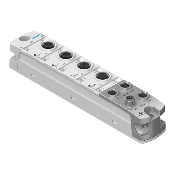
Connection for power supply [XD1] Mounting interface connection side bottom and functional earth FE connection Mounting interface, lateral bottom and con- nection for functional earth FE Inscription label (optional) Mounting interface, lateral top Fig. 1: Product design Festo — CPX-AP-I-4IOL-M12 — 2022-03a... -
Page 7: Led Displays
Status/diagnostics of IO-Link port 2 [X2.2] (green, red, yellow) Status/diagnostics of IO-Link port 1 [X1.1] (green, red, yellow) Status/diagnostics of IO-Link port 0 [X0.0] (green, red, yellow) Status/diagnostics for load supply [PL] (green, red) Fig. 2: LED displays Festo — CPX-AP-I-4IOL-M12 — 2022-03a... -
Page 8: Connecting Elements
Tab. 5: Connection for voltage forwarding Connection for system communication [XF10] Socket M8, 4-pin, D-coded Signal TX– Transmitted data – Received data + Transmitted data + RX– Received data – Tab. 6: Connection for system communication Festo — CPX-AP-I-4IOL-M12 — 2022-03a... -
Page 9: Assembly
When connecting Devices Class A with 4 or 5-pin cables, do not connect pins 2 and 5. Commissioning • Commission the automation system CPX-AP-I in accordance with the operating instructions for the automation system CPX-AP-I è 1.1 Applicable documents. Festo — CPX-AP-I-4IOL-M12 — 2022-03a... - Page 10 Tab. 9: Response of the LED displays of the module after error-free commissioning Information on troubleshooting in the event of incorrect behaviour: è Instruction manual for automation system CPX-AP-I è 1.1 Applicable documents è 9 Diagnostics and fault clearance Festo — CPX-AP-I-4IOL-M12 — 2022-03a...
-
Page 11: Address Space (Data Length Inputs/Outputs)
4) Factory setting Tab. 10: Variants for setting the address space The "Festo IO-Link Tool" software can be used to set the address space (data length inputs/outputs) è www.festo.com/sp. The setting is saved permanently in the module. Changes only become effective after a restart of the automation system CPX-AP. -
Page 12: Io-Link Device Description File (Io-Link Device Description)
Bit 0 Tab. 12: Port Qualifier Information (PQI) IO-Link Device description file (IO-Link Device Description) The "Festo IO-Link Tool" software can be used to configure a IO-Linkdevice è www.festo.com/sp. Search by part number or type, download in "Software" section. Parameterisation Various parameters are available for reading out information about the modules in an automation system CPX-AP and adapting the modules to the application situation. - Page 13 20050 Activation of diagnostics for IO-Link BOOL – device lost (factory setting TRUE) 20071 Port mode UINT8 – – 0: DEACTIVATED (factory setting) – 1: IOL_MANUAL – 2: IOL_AUTOSTART – 3: DI_CQ – 97: PREOPERATE Festo — CPX-AP-I-4IOL-M12 — 2022-03a...
- Page 14 – – 0: not detected – 1: COM1 – 2: COM2 – 3: COM3 20077 Actual cycle time [in 100 µs] UINT16 – 20078 Actual vendor ID UINT16 – 20079 Actual device ID UINT32 – Festo — CPX-AP-I-4IOL-M12 — 2022-03a...
- Page 15 – 8213: variant 32 OE 20093 Hardware version UINT8 – 20097 Activation of the operating voltage BOOL – supply for all 4 ports (factory setting TRUE) 1) ro = read only; rw = read write Tab. 15: AP parameter Festo — CPX-AP-I-4IOL-M12 — 2022-03a...
-
Page 16: Diagnostics And Fault Clearance
– Remedy Diag- Error nostic status 02 | 01 | 0016 Undervoltage in logic Undervoltage in logic supply (PS) 24 V DC (33619990) supply (PS) 24 V DC – Check power supply. Abhilfe Festo — CPX-AP-I-4IOL-M12 — 2022-03a... - Page 17 – Check firmware versions Remedy Diag- Error nostic status 08 | 00 | 0135 Wirefracture detected Wirefracture detected (134218037) – Check wiring Remedy Diag- Error nostic status Festo — CPX-AP-I-4IOL-M12 — 2022-03a...
- Page 18 – Adapt cycle time to permissable value Remedy Diag- Error nostic status 08 | 0A | 014D Revision fault – Revision fault – incompatible IO-Link protocol version (134873421) incompatible protocol – Device not compatible Remedy version Festo — CPX-AP-I-4IOL-M12 — 2022-03a...
- Page 19 – Change module variant to a bigger process Remedy data length Diag- Error nostic status 08 | 0A | 0182 Device Event overflow Too many IO-Link Events. Events might be lost. (134873474) – Remedy Diag- Error nostic status Festo — CPX-AP-I-4IOL-M12 — 2022-03a...
- Page 20 – Check if correct IO-Link device is connected Remedy Diag- Error nostic status 08 | 0A | 01A9 No Device No Device (communication) (134873513) – Check if IO-Link device is connected Remedy Diag- Error nostic status Tab. 16: Diagnostic messages Festo — CPX-AP-I-4IOL-M12 — 2022-03a...
-
Page 21: Led Displays
PL red light Module ramp-up not yet completed. – System communication not yet initial- ised. fast red flashing Module identification (service function) – fast green flashing Tab. 17: LED module diagnostics [MD] Festo — CPX-AP-I-4IOL-M12 — 2022-03a... - Page 22 Load supply PL not available. Check load supply PL. flashing green 0.5 Hz Load supply PL outside the tolerance Check load supply PL. range. flashing red 0.5 Hz Tab. 18: LED load supply [PL] Festo — CPX-AP-I-4IOL-M12 — 2022-03a...
- Page 23 Device not compatible with set configu- ration (è parameter 20072). Pending error of the Device Read out diagnostic messages and carry out corresponding remedial measures è 9.1 Diagnostic messages. flashing red Tab. 19: LED IO-Link Port 0... 3 Festo — CPX-AP-I-4IOL-M12 — 2022-03a...
-
Page 24: Event Codes
Startup parameter The startup parameter specified in the AP (100663561) rejected by device device description does not exist in the device or is different from the specification. – Check firmware versions Abhilfe Diagnoses- Error tatus Festo — CPX-AP-I-4IOL-M12 — 2022-03a... - Page 25 IO-Link Backup/Restore failed. Data Storage (134873477) – Data Storage unspecific error unspecific error – Device specific Abhilfe Diagnoses- Error tatus 180Ch 08 | 0A | 0177 Backup inconsistency IO-Link Backup/Restore failed. Upload fault (134873463) – upload fault – Abhilfe Festo — CPX-AP-I-4IOL-M12 — 2022-03a...
- Page 26 Diagnoses- Error tatus 6000h 08 | 0A | 014C Invalid cycle time Invalid cycle time of IO-Link communication (134873420) – Adapt cycle time to permiss- Abhilfe able value Diagnoses- Error tatus Festo — CPX-AP-I-4IOL-M12 — 2022-03a...
-
Page 27: Device Event Codes
General malfunction – unknown error of IO- (218104129) IO-Link Device Link Device. Corresponds to IO-Link Even- tCode 0x1000. – Check IO-Link Device Abhilfe Diagnoses- Information tatus 1805h 03 | 01 | 0181 PHY overtemperature IO-Link PHY exceeds permissable tempera- (50397569) ture Festo — CPX-AP-I-4IOL-M12 — 2022-03a... - Page 28 – Check drive dimensioning (possible overload in contin- uous operation) Diagnoses- Error tatus 4220h 03 | 01 | 002D Insufficient tempera- Insufficient temperature in device (50397229) ture in device – Check ambient conditions Abhilfe Festo — CPX-AP-I-4IOL-M12 — 2022-03a...
- Page 29 – Eliminate cause of blown fuse Diagnoses- Error tatus 5110h 02 | 01 | 0017 Overvoltage in logic Overvoltage in logic supply (PS) 24 V DC (33619991) supply (PS) 24 V DC – Check power supply. Abhilfe Diagnoses- Warning tatus Festo — CPX-AP-I-4IOL-M12 — 2022-03a...
- Page 30 01 | 01 | 0162 Ground fault – Check Ground fault – Check installation (16843106) installation – Check installation Abhilfe Diagnoses- Error tatus 8C01h 0D | 00 | 0164 Simulation active Simulation active (218104164) – Check operational mode Abhilfe Festo — CPX-AP-I-4IOL-M12 — 2022-03a...
- Page 31 0C | 01 | 016A Maintenance required Maintenance required – Exchange wear and (201392490) – Exchange wear and tear parts tear parts – Exchange wear and tear parts Abhilfe Diagnoses- Warning tatus Tab. 22: IO-Link device Eventcodes Festo — CPX-AP-I-4IOL-M12 — 2022-03a...
-
Page 32: Technical Data
(protection (safe extra-low voltage/protected extra-low voltage) against direct and indi- rect contact in accord- ance with IEC 60204-1) Electromagnetic com- See declaration of conformity è www.festo.com patibility Mounting position Tab. 23: General technical data Festo — CPX-AP-I-4IOL-M12 — 2022-03a... - Page 33 Capacitive load at load supply PL 24 V PL to 0 V PL [nF] Typically 35 24 V PL to FE [nF] Typically 35 0 V PL to FE [nF] Typically 20 Tab. 24: Power supply Festo — CPX-AP-I-4IOL-M12 — 2022-03a...
- Page 34 > 0.7 Internal voltage drop Max. current PL 4/1.5; not on all ports simultaneously per module/Port PL short-circuit protec- tion External fuse protection via circuit breaker required. PL reverse polarity pro- Yes (internal only) tection Festo — CPX-AP-I-4IOL-M12 — 2022-03a...
- Page 35 Technical data IO-Link Ports (in accordance with IO-Link specification V1.1) Electrical isolation Between the ports Between PS and PL Tab. 25: IO-Link Ports Festo — CPX-AP-I-4IOL-M12 — 2022-03a...
- Page 36 Copyright: Festo SE & Co. KG 73734 Esslingen Ruiter Straße 82 Deutschland Phone: +49 711 347-0 Internet: © 2022 all rights reserved to Festo SE & Co. KG www.festo.com...
Need help?
Do you have a question about the CPX-AP-I-4IOL-M12 and is the answer not in the manual?
Questions and answers