Launch X-431 PAD V User Manual
Hide thumbs
Also See for X-431 PAD V:
- User manual (106 pages) ,
- Quick start manual (3 pages) ,
- Online manual (4 pages)
Table of Contents
Advertisement
Quick Links
LAUNCH
WARNING SYMBOLS AND DEFINITIONS
This safety alert symbol is used to alert you
to potential injury hazards. Obey all safety
messages that follow this symbol to avoid
possible injury.
Indicates an imminently hazardous situation
which, if not avoided, could result in death or
serious injury to the operator or to bystanders.
Indicates a potentially hazardous situation
which, if not avoided, could result in death or
serious injury to the operator or to bystanders.
Indicates a hazardous situation which, if not
avoided, could result in minor or moderate
injury to the operator or to bystanders.
Addresses practices not related to personal
injury.
IMPORTANT SAFETY INFORMATION
When an engine is operating, keep the service area well-ventilated
or attach a building exhaust removal system to the engine
exhaust system. Engines produce various poisonous compounds
(hydrocarbon, carbon monoxide, nitrogen oxides, etc.) that cause
slower reaction time and result in death or serious personal injury.
Read all safety warnings and instructions.
*Note: Failure to follow the warnings and instructions may result in
electric shock, fi re and/or serious injury.
1. Always perform automotive testing in a safe environment.
2. Do not connect or disconnect any test equipment while the ignition
is on or the engine is running.
3. DO NOT attempt to operate the tool while driving the vehicle.
Have second personal operate the tool. Any distraction may
cause an accident.
4. Before starting the engine, put the gear lever in the Neutral
position (for manual transmission) or in the Park (for automatic
transmission) position to avoid injury.
5. NEVER smoke or allow a spark or flame in vicinity of battery or
engine. Do not operate the tool in explosive atmospheres, such as
in the presence of fl ammable liquids, gases, or heavy dust.
6. Keep a fire extinguisher suitable for gasoline/chemical/electrical
fi res nearby.
7. Wear an ANSI-approved eye shield when testing or repairing
vehicles.
8. Put blocks in front of the drive wheels and never leave the vehicle
unattended while testing.
9. Use extreme caution when working around the ignition coil,
distributor cap, ignition wires and spark plugs. These components
create hazardous voltage when the engine is running.
10. To avoid damaging the tool or generating false data, please make
sure the vehicle battery is fully charged and the connection to the
vehicle DLC (Data Link Connector) is clear and secure.
User's Manual
PAD V
I
Advertisement
Table of Contents

Related Manuals for Launch X-431 PAD V


Summary of Contents for Launch X-431 PAD V
- Page 1 LAUNCH User's Manual PAD V WARNING SYMBOLS AND DEFINITIONS This safety alert symbol is used to alert you Read all safety warnings and instructions. to potential injury hazards. Obey all safety *Note: Failure to follow the warnings and instructions may result in messages that follow this symbol to avoid electric shock, fi...
-
Page 2: Table Of Contents
LAUNCH User's Manual PAD V 11. Automotive batteries contain sulfuric acid that is harmful to skin. Table of Contents In operation, direct contact with the automotive batteries should be avoided. Keep the ignition sources away from the battery at all 1 Introduction ..................1... - Page 3 5.1.3 Vehicle Connection (For Passenger Vehicle Version) ..16 5.5.3 Start Instant Messaging ............36 5.1.3 Vehicle Connection (For Commercial Vehicle Version/Diesel 5.5.4 Launch Remote Diagnosis (Device-To-Device) ....37 & Gasoline Version) ..............17 5.5.5 Launch Remote Diagnosis (Device-To-PC) ......38 5.2 Communication Setup ..............18 5.6 Diagnostic History.................40...
- Page 4 LAUNCH User's Manual PAD V 6.13.2 Shop Information ...............47 7.3.1 Introduction ................72 6.13.3 Printer Set................47 7.3.2 Structure & Accessories ............72 6.13.4 Clear Cache...............48 7.3.3 Connection & Initial Use ............75 6.13.5 About .................48 7.3.4 Operations ................79 6.13.6 Diagnostic Software Auto Update ........48 7.4 Ignition (Optional) .................85...
-
Page 5: Introduction
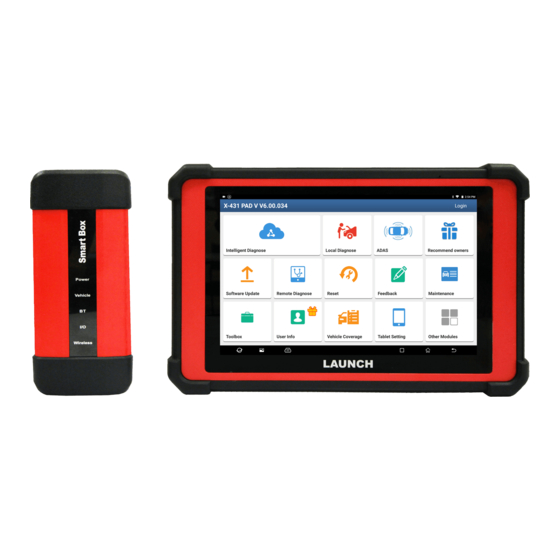
1.1 Product Profi le • Maintenance & Reset: All kinds of common maintenance and X-431 PAD V is an evolutionary smart solution for specialized reset items including Oil lamp reset, DPF regeneration, ABS automotive diagnosis and maintenance. It inherits from LAUNCH’s bleeding can be done. -
Page 6: Technical Specifi Cations
LAUNCH User's Manual PAD V 1.3 Technical Specifi cations B. VCI Device A. Display Tablet Item Description DC 9V ~ 36V Item Description Working voltage Android 256MB Operating system Memory 8-core processor, 2GHz 10.1 inch capacitive touch screen with Type B x 1... -
Page 7: Components & Controls
LAUNCH User's Manual PAD V 2 Components & Controls There are three main components to the diagnostic system: • Display Tablet -- the central processor and monitor for the system (For details, please refer to Chapter 2.1.) Fig. 2-3 Fig. 2-1 •... -
Page 8: Display Tablet
LAUNCH User's Manual PAD V Table 2-1 formulates ports and indicators of display tablet: 2.1 Display Tablet Name & Descriptions Memory Card Slot -- To store the memory card for storage expansion. Type C Charging Port -- Reserved for charging the tablet. -
Page 9: Docking Station (Optional)
LAUNCH User's Manual PAD V 2.2 Docking Station (Optional) Fig. 2-6 Docking Station Table 2-3 formulates ports of the docking station Fig. 2-5 Rear view Name & Descriptions Table 2-2 formulates parts of display tablet (rear): Charging Slot -- To charge the tablet. -
Page 10: Vci Device
LAUNCH User's Manual PAD V 2.3 VCI Device Table 2-4 formulates ports and indicators of VCI device: The VCI device works as a vehicle communication interface device, Name & Descriptions which is used to connect to the vehicle’s DLC (Data Link Connector) -
Page 11: Accessory Checklist
LAUNCH User's Manual PAD V 2.4 Accessory Checklist Common accessories are same, but for different destinations, the accessories (such as diagnostic software, testing connectors) may Cigarette Lighter vary. Please consult from the local agency or check the package list (To supply power to non-16pin Cable supplied with this tool together. - Page 12 LAUNCH User's Manual PAD V OBD II extension cable (To connect the VCI device for extension purpose.) OBD I Adaptor (A adaptor cable for connecting non-16 pin dongle.) Password Envelope (A piece of paper bearing Product S/N and Activation Code, which is required for your registration.)
-
Page 13: Preparations
LAUNCH User's Manual PAD V 3 Preparations B. Charging with the Docking Station 1. Locate the charging slot on the 2. Align the charging slots, and 3.1 Charging the Tablet bottom of the tablet and docking then dock the tablet into the station. -
Page 14: Locator & Navigation Buttons
If the VCI device is successfully activated, the tablet will automatically connect to the VCI device. In this case it is not necessary for the user to visit the Launch’s offi cial website. to manually confi gure it again. to capture the current screen and all captured *Note: Once WLAN is set as ON, the tablet will consume more power. -
Page 15: Initial Use
PAD V 4.2 Register & Download Diagnostic Software 4 Initial Use On the home screen, tap the application icon to launch it, and then tap “Login” to enter the login interface of diagnosis software. 4.1 Getting Started For new users, please follow the operation chart shown in Fig. 4-1 to get familiar with and start using this tool. - Page 16 LAUNCH User's Manual PAD V will appear: Fig. 4-6 To download the diagnostic software, tap “Yes” to enter the download page. Tap “No” to download and install it later. Fig. 4-4 On download page, tap “Update” to start downloading. To pause In Fig.
-
Page 17: Function Modules
To update vehicle diagnostic software and Software Update APK. This option aims to help repair shops or technicians launch instant messaging and Remote Diagnose remote diagnosis, making the repair job getting fi xed faster. To perform all kinds of common repair &... -
Page 18: Vehicle Menu Layout
LAUNCH User's Manual PAD V VINScan button: Tap it to scan the Vehicle Identification Includes TeamViewer, Email, Browser, Other Modules Number (VIN) code of your vehicle. OBD VIN and INPUT VIN Wireless Upgrade and FAQ etc. are included. This function does not apply to the commercial vehicles. - Page 19 LAUNCH User's Manual PAD V the upper right corner of the screen and goes through the whole diagnostic session. The table below provides a brief description for the operations of the diagnostics toolbar buttons: Tap to navigate to the home screen.
-
Page 20: Start Diagnostics
LAUNCH User's Manual PAD V to the vehicle’s service manual for the location. 5 Start Diagnostics 5.1 Connections 5.1.1 Preparation Normal testing conditions • Turn on the vehicle power supply. • Vehicle battery voltage range should be 9-18V or 11-36V and working voltage of the tablet is 5V. -
Page 21: Vehicle Connection (For Commercial Vehicle Version/Diesel & Gasoline Version)
LAUNCH User's Manual PAD V For non-OBDII vehicle, proceed as follows: Battery clamps cable To vehicle's battery 1. Locate vehicle’s DLC socket. 2. Select the corresponding non-16pin dongle. VCI device OBD I adaptor Non-16pin adaptor 3. Plug the non-16pin end of the non-16pin adaptor into the DLC socket, then connect the other end to the OBD I adaptor, and then tighten the captive screws. -
Page 22: Communication Setup
LAUNCH User's Manual PAD V properly connecting the USB cable from the tablet to the VCI, the VCI Cigarette lighter To Cigarette lighter receptacle navigation button at the bottom of the screen becomes highlighted indicating the USB connection is successful. - Page 23 LAUNCH User's Manual PAD V records available, it will be listed on the screen in sequence of date. If no records exist, the screen will show “No Record”. Fig. 5-6 2. After pairing is complete, the handset starts reading the vehicle Fig.
-
Page 24: Local Diagnosis
In this mode, you need to input the VIN manually or tap to scan it. 1) Tap to launch the VIN recognition module. Fig. 5-11 • If the VIN scanned is incorrect, tap the result fi eld to modify it and then tap “OK”. - Page 25 LAUNCH User's Manual PAD V In this case, automatic scan (OBD VIN) and manual input (INPUT VIN) • To switch the display orientation, tap are available. • To turn the fl ash on, tap Tap “VINScan”, the screen displays as follows: •...
- Page 26 LAUNCH User's Manual PAD V Input the VIN, and tap “Confirm”, the system will automatically OK: Tap it to go to next step. identify the vehicle model and directly navigate to the function 2). Select test item: Select the desired test item to proceed.
- Page 27 LAUNCH User's Manual PAD V *Note: Diagnostic Trouble Codes or Fault Codes can be used to identify which engine systems or components that are malfunctioning. Never replace a part based only on the DTC definition. Retrieving and using DTCs for troubleshooting vehicle operation is only one part of an overall diagnostic strategy.
- Page 28 LAUNCH User's Manual PAD V *Note: Diagnostic report is classified into three categories: Pre-Repair report, Post-Repair report and Diagnostic Scan. No matter which type you saved the report as, the report type will be appended as a tag on the upper right corner of the diagnostic report for easier identifi...
- Page 29 LAUNCH User's Manual PAD V The DTC status The DTC status 5.3.2.2 System Scan post-repair pre-repair This option allows you to quickly scan which systems are installed on the vehicle. In Fig. 5-16, tap “System Scan”, the system starts scanning the systems.
- Page 30 LAUNCH User's Manual PAD V A. Version Information This function is used to read the version information of system mode, vehicle VIN, software and ECU. In Fig. 5-25, tap “Version Information”, the screen displays as follows: Fig. 5-26 Fig. 5-24 Tap “OK”...
- Page 31 LAUNCH User's Manual PAD V *Note: Retrieving and using DTCs for troubleshooting vehicle operation *Note: After clearing, you should retrieve trouble codes once more or turn is only one part of an overall diagnostic strategy. Never replace a part ignition on and retrieve codes again. If there are still some trouble codes in based only on the DTC defi...
- Page 32 LAUNCH User's Manual PAD V On-screen Buttons: • Value – this is the default mode which displays the parameters in texts and shows in list format. Select All: Tap it to select all items of the current page. To select certain data stream item, just check the box before the item name.
- Page 33 LAUNCH User's Manual PAD V will display/remove the waveforms corresponding to these items immediately. Fig. 5-31 • Combine: This option is mostly used in graph merge status for data comparison. Fig. 5-33 Select Sample DS: Tap it to select the sample DS fi le, the values you customized and saved in process of DS sampling will be imported into the “Standard Range”(See below) column for your comparison.
- Page 34 LAUNCH User's Manual PAD V Fig. 5-34 Fig. 5-35 Report: To save the current data as a diagnostic report. All diagnostic Once recording is complete, tap to stop it and navigate to the data reports can be accessed from “User Info” -> “My Reports” -> “Health revision screen.
-
Page 35: Maintenance Reset
LAUNCH User's Manual PAD V • Diesel Particulate Filter (DPF) Regeneration • Electronic Throttle Position Reset • Gearbox Matching • AFS (Adaptive Front-lighting System) Reset • Sunroof Initialization • Suspension Calibration There are two methods to reset service lamp: Manual reset or Auto reset. -
Page 36: Electronic Parking Brake Reset
LAUNCH User's Manual PAD V vehicle driving conditions and climate. 5.4.4 ABS Bleeding This function can be performed in the following cases: This function allows you to perform various bi-directional tests to check the operating conditions of Anti-lock Braking System (ABS). -
Page 37: Immo Service
LAUNCH User's Manual PAD V After the engine ECU, crankshaft position sensor, or crankshaft 5.4.8 Injector Coding fl ywheel is replaced, or the DTC ‘tooth not learned’ is present, tooth Write injector actual code or rewrite code in the ECU to the injector learning must be performed. -
Page 38: Electronic Throttle Position Reset
LAUNCH User's Manual PAD V DPF regeneration may be performed in the following cases: 5.4.14 Sunroof Initialization a) The exhaust back pressure sensor is replaced. This function can set the sunroof lock off, closed when it rains, sliding / tilting sunroof memory function, temperature threshold outside the car b) The PM trap is removed or replaced. -
Page 39: Remote Diagnosis
Tap “Contact” to enter the contact page. By default it appears blank. In the search bar, input the partner’s username and tap “Search” button next to the search bar to starts searching from Launch’s golo business database. The partner must be the users who have registered their Launch’s diagnostic tools. -
Page 40: Start Instant Messaging
5.5.3 Start Instant Messaging Fig. 5-43 *Note: The I/M (Instant Messaging) function is open to all users who had File: Choose diagnostic reports or local fi les to send. Launch’s diagnostic tool equipped with this module. Picture: Choose screenshots or pictures to send. -
Page 41: Launch Remote Diagnosis (Device-To-Device)
*Notes: The tablet is allowed to initiate remote diagnosis with other diagnostic • Remote diagnosis has the same diagnostic tools (including but not limited to this product) of Launch family, which steps as manual diagnosis. are equipped with this module. -
Page 42: Launch Remote Diagnosis (Device-To-Pc)
5.5.5 Launch Remote Diagnosis (Device-To-PC) *Notes: cept that the remote diagnosis can e done et een different • Remote diagnosis has the same diagnostic aunchs diagnostic tools that come loaded ith the module, user also steps as manual diagnosis. - Page 43 LAUNCH User's Manual PAD V Fig. 5-45 Tap the “Web Remote” tab, the screen displays as follows: Fig. 5-47 3. Tell the partner to input his own official technician account and Fig. 5-46 password, and then tap “Login” to navigate to the following fi gure.
-
Page 44: Diagnostic History
LAUNCH User's Manual PAD V Serial Number provided by you, and then tap “Start remote report. diagnosis” to control your device remotely. • To delete certain diagnostic history, select it and then tap “Delete”. In process of remote diagnosis, please note the following things: To delete all historical records, tap “Select All”... -
Page 45: Set Frequently Used Software
LAUNCH User's Manual PAD V software, tap “Unselect”, and then check the box next to vehicle 5.8 Store model. Tap “Update” to start downloading. It may take several minutes If the software subscription is due or expires, user can go to “Local to fi... -
Page 46: Adas
(optional) before performing this function. Moreover, it also requires the diagnostic tool to work with the X-431 ADAS PRO calibration tool manufactured by LAUNCH (calibration tools from other manufacturers will not be supported). As a comprehensive and flexible calibration tool, the X-431 ADAS PRO calibration tool enables you to effectively and accurately calibrate a wide range of camera-based &... -
Page 47: Feedback
LAUNCH User's Manual PAD V 2. Tap “Activate” to enter the ADAS activation screen. column of the screen. A. Feedback Tap a tested vehicle model to enter the feedback screen. 1) Tap “Choose File” to open the target folder and choose the desired diagnostic logs. -
Page 48: User Info
LAUNCH User's Manual PAD V will be saved as .x431 fi le and appear under Recorded Data tab. 6 User Info 6.1 My Report This option is used to view, delete or share the saved reports. Tap “My Report”, there are total 3 options available. -
Page 49: Vci
Once it is in frame playback mode, this button changes into diagnostic socket. “Auto Playback”. Please bind X-PROG to LAUNCH-specifi c diagnostic tool before using Remote Diagnostic Report lists all diagnostic reports generated in to ensure they can work together. -
Page 50: Activate Vci
LAUNCH User's Manual PAD V when the VCI is plugged into the vehicle’s DLC. 6.4 Activate VCI This item lets you activate a new VCI device. 6.9 My Order This item allows you to check the status of all your orders. -
Page 51: Change Password
Tap “Scan” to start scanning and select the desired printer hotspot hotspot). named with X-431PRINTER-XXXX (XXXX stands for 4 characters), Here we take “LAUNCH printer” for example to demonstrate how to and then tap “Connect” to enter Step 2. confi gure the printer. -
Page 52: Clear Cache
LAUNCH User's Manual PAD V password is not required), and then tap “Confi rm”. 6.14 Diagnostic Software Clear 4. Once the Wi-Fi network of the printer is connected and the printer This item allows you to hide/clear the diagnostic software that is not is found, tap “Printing test”... -
Page 53: Toolbox
LAUNCH User's Manual PAD V 7 ToolBox Square-wave signal pulse frequency 0~15KHz Square-wave signal duty ratio 10%~90% 7.1 Sensorbox & Multimeter (Optional) Multimeter 7.1.1 Product summary The tablet provides an optional function of automotive sensor Parameters Scope simulation test. “Sensor” function is specially designed to diagnose Precision ±5%... -
Page 54: Components And Accessories
LAUNCH User's Manual PAD V 7.1.2 Components and Accessories Connect to power supply through the Power Interface power adaptor. 7.1.2.1 Components & controls Common terminal of multimeter VΩHz Testing terminal of multimeter 7.1.2.2 Accessories The Sensorbox accessories include sensor test cable, probe etc. For detailed items, please see the packing list. -
Page 55: Sensor Simulation
LAUNCH User's Manual PAD V 7.1.3 Sensor Simulation 7.1.3.1 Connections 1. Firstly, power on the diagnostic tool. Power adapter 2. Connect the B-shaped terminal of data cable to the B-shaped port of the Sensorbox, and the other end to the Data I/O port of the To supply power to the diagnostic tool. - Page 56 LAUNCH User's Manual PAD V launch the application and enter the “Toolbox” function menu interface, then tap “Sensor” to enter the test selection screen. Tap the setting option tab, then tap “+” or “-” to adjust the output,After setting, tap to perform the test.
- Page 57 LAUNCH User's Manual PAD V MAF: Mass Air Flow Sensor MAP: Manifold Absolute Pressure Sensor TP: Throttle Position Sensor VAF: Volume Air Flow Sensor VSS: Vehicle Speed Sensor For example, tap “ECT” – “Warm (NTC Thermistor)”, the right screen will display the waveform of the sensor.
- Page 58 LAUNCH User's Manual PAD V PWS-3 Button descriptions: ]: Save the current waveform. button to perform simulation test. ]: Loads the previously saved hand-drawn waveform. 4. Hand-painted waveform simulation ]: Clear all hand-drawn waveform. This option offers great convenience for users to simulate special ]: Tap to call out the predefi...
-
Page 59: Multimeter
LAUNCH User's Manual PAD V measured, and the black probe to the ground when measuring example for demonstration. voltage of one terminal/ one cable. • When checking the continuity of the terminals, contacts and leads, the method for measuring their resistances can be used. -
Page 60: Battery Tester (V1.0, Optional)
LAUNCH User's Manual PAD V (2) Checking for the output signal of knock sensor 7.2 Battery Tester (V1.0, Optional) Unplug the wire connector of knock sensor, check voltage between 7.2.1 Product Summary knock sensor connector terminal and ground wire of knock, it should be output pulse voltage;... -
Page 61: Test Environment
LAUNCH User's Manual PAD V Society of Automotive Stands for low battery. The battery is good 100~1700 Good-recharge Engineers itself. It is better for a few batteries to be fully 7.2.2 Test Environment Charge-retest charged before testing in order to avoid judging in error under special conditions. -
Page 62: Connections & Operations
LAUNCH User's Manual PAD V Below describes the ports and indicators for the Batterybox. end to the Data I/O port of the diagnostic tool. This connection applies to outside the vehicle test and inside the vehicle. Name Descriptions *Notes: It keeps solid red after the Scopebox is 1. - Page 63 LAUNCH User's Manual PAD V or by dragging the slider on the bar. *Note: The sequences of inside the vehicle and outside the vehicle test are almost the same, but under inside the vehicle condition, all loads in vehicles must be powered off for getting an exact test value.
-
Page 64: Precautions On Battery Test
LAUNCH User's Manual PAD V The following operation steps are identical to Steps 6 ~ 7 in Chapter ]: Tap it to reset the test. 7.2.4.2 Battery test. Please refer to it for details. 2. Charging system and starting system test 7.2.5 Precautions on battery test... - Page 65 LAUNCH User's Manual PAD V low capacity. In this case, just recharge your battery. Bad cell always happens when the loads on a stopping vehicle are turned on for a long time. Please note that it is normal for quick detecting of “Increase speed”...
-
Page 66: Battery Detection (V2.0, Optional)
LAUNCH User's Manual PAD V 7.2 Battery Detection (V2.0, Optional) Society of Automotive 100 ~ 1700 Engineers 7.2.1 Product Summary Adopting the state-of-the-art conductance testing technology in the 7.2.1.2 Components & Controls world, the vehicle battery diagnostic tool provides the excellent ability to test vehicle’s battery status. - Page 67 2. POWER LED - illuminates RED if the battery tester has been powered up. 3. Data I/O Port - connects the battery tester to the diagnostic tool via data cable so that the signal can be displayed on the tool. Launch-specifi c diagnostic tool 4. Handle 5.
-
Page 68: Battery Health Test
LAUNCH User's Manual PAD V current is normal. 7.2.1.5 Main Menu Generate report This option is used to save the reports after the battery health test, start system test and the charging health test are successfully performed. Historical report Manages the saved reports. - Page 69 LAUNCH User's Manual PAD V Follow the on-screen prompts to turn on the headlamp to remove it. 3. After selecting the battery type, the system detects whether fl oating electricity exists or not before testing (To skip this step, tap “Cancel fl...
- Page 70 LAUNCH User's Manual PAD V B). If no fl oating electricity is detected, the system will go to the next JIS battery capacity selection screen step directly. B). If selecting a testing standard other that JIS, users can adjust 4. Select the desired battery testing standard and capacity.
-
Page 71: Start System Test
LAUNCH User's Manual PAD V It is better for a few batteries to be fully charged before testing in order Charge-retest to avoid judging in error under special conditions. Indicates one of the battery cells is bad and can not work normally, but for which one is bad, it can’t be verifi... -
Page 72: Charging Health Test
LAUNCH User's Manual PAD V *Note: It is unnecessary to perform this test after finishing battery health test, but battery test must be done before undergoing this test. Follow the steps below to proceed: 1. Tap "Start System Test" on the battery main menu, the following operation tips will pop up on the screen. - Page 73 LAUNCH User's Manual PAD V *Notes: • Please start the engine before test. • It is unnecessary to perform this test after finishing battery health test, but battery test must be done before undergoing this test. Follow the steps below to proceed: 1.
-
Page 74: Reports
LAUNCH User's Manual PAD V *Notes: • On-load voltage refers to the charging voltage when there is a load. It evaluates the on-load capacity of the generator. When different auto parts are opened, the load voltage will be generated. The on-load voltage will greatly vary depending on the auto parts being opened. - Page 75 LAUNCH User's Manual PAD V will pop up on the screen. Scan the QR code on the screen with smart phone to view the report details. Tap the desired report to view its details. To delete certain report, select it and then tap "Delete record".
-
Page 76: Oscilloscope (Optional)
LAUNCH User's Manual PAD V 7.3.2 Structure & Accessories 7.3 Oscilloscope (Optional) 7.3.2.1 Scopebox structure 7.3.1 Introduction The Scopebox is an optional add-on module of this tablet, including automotive oscilloscope and automotive ignition waveform. Automotive oscilloscope can make the auto repair technician quickly... - Page 77 LAUNCH User's Manual PAD V External trigger signal (*It only applies if the Name Description External trigger Scopebox failed to trigger the signal itself.) Connect to the diagnostic tool via data B-shaped data I/ cable so that the signal can be displayed on O port the tool.
- Page 78 LAUNCH User's Manual PAD V BNC Connector Data Cable Crocodile Clip Connects the Scopebox and diagnostic tool so that the sampled signal can be displayed on the diagnos c tool. High-voltage Clip This ignition pick-up is applied in the Power adapter...
-
Page 79: Connection & Initial Use
Multimeter 2. Follow Steps 1-2 in Item 2 "Connection" mentioned below to probes connect the Scopebox and diagnostic tool. Launch the App and open "Scope" to run it. 3. From the "Vertical Setting" menu, select the corresponding channel and set the Probe attenuation to 1:10. - Page 80 LAUNCH User's Manual PAD V Probe Compensator To avoid electric shock while using the probe, make sure the insulated cable is perfect, and do not touch the metallic portions of the probe head while it is connected with a high-voltage source.
- Page 81 LAUNCH User's Manual PAD V BNC to 4mm High-voltage clips to test lead high-voltage line 6-way breakout lead Black connector to Black socket Red connector to the other color Connect to socket any Channel Crocodile clips to ground Scopebox BNC Connectors 4.
- Page 82 LAUNCH User's Manual PAD V high-voltage line, and crocodile clips to ground. The connection is as follows: Ignition coil COP earth cord Spark plug COP earth cord & crocodile clips to ground Displays the CH1/CH2/CH3/CH4 information: Readout shows the coupling and vertical scale factors of the...
-
Page 83: Operations
LAUNCH User's Manual PAD V There are two ways available for channel selection: Horizontal Settings Panel: Controls the time base. A. Select from the channel tab shown at the bottom of the waveform Vertical Settings Panel: Controls the amplitude of the display area displayed signal. - Page 84 LAUNCH User's Manual PAD V (using the button), the Time/DIV selector expands or compresses • DC: Passes both AC and DC components of the input signal. the waveform. • Ground: Disconnects the input signal. Y-T format: The conventional oscilloscope display format. It shows the...
- Page 85 LAUNCH User's Manual PAD V Sweep: The sweep mode determines how the Scopebox behaves in does not detect a trigger condition. If no trigger condition occurs the absence of a trigger event. The Scopebox provides three trigger while the Scopebox is waiting for a specifi c period, it will force itself modes: Auto, Normal, and Single.
- Page 86 LAUNCH User's Manual PAD V and then tap [Calibration], a dialog box similar to the following fi gure will appear. Tap < or > to select the desired reference value for time/DIV and volts/ DIV. To show or hide the REF, just check/uncheck the box before On/ Off.
- Page 87 LAUNCH User's Manual PAD V <3> Clear measure and then [Clear Measure], the system will clear the measurement result on screen. 7.3.4.5 File management <1> Save snapshot While viewing sampling data, tap and then [Save Snapshot] to store the current screen.
- Page 88 LAUNCH User's Manual PAD V frames, and [Stop] to stop recording. While recording, the recorded To delete the waveform fi le, tap pages will be shown on the screen. to return to the previous screen. <4> Load waveform for playback 7.3.4.6 Expert reference...
-
Page 89: Ignition (Optional)
LAUNCH User's Manual PAD V Preset waveforms of some sensors are available for your reference. 7.4 Ignition (Optional) The ignition system is the system which has greatest impact on the performances of gasoline engine, as the statistical data shows that nearly half of the failures are caused by poor work of electrical system. - Page 90 LAUNCH User's Manual PAD V 1. Power the Scopebox on: Power is provided to the Scopebox in IA-1 below shows the normal ignition waveform of distributor ignition either of the following ways: system, the upper one is the secondary waveform, and the lower one is the primary waveform.
-
Page 91: Secondary-Simultaneous Ignition Analysis
LAUNCH User's Manual PAD V inductance voltage of ignition coil maintains the conduction of two terminals to the vehicle's battery (Red to +, and Black to -) secondary circuit. respectively. 6) Contact point close the current fl ow into primary coil, the primary 2. -
Page 92: Secondary-Direct Ignition Analysis
LAUNCH User's Manual PAD V cylinder. Connect one end of the COP extension cord to the ignition coil which should be grounded via COP earth cord, and insert the other end into the cylinder to joint with spark plug. Then plug the... -
Page 93: Waveform Analysis Mode
LAUNCH User's Manual PAD V oscillations within the duration, but the voltage increases during the be performed during driving. Since the secondary ignition waveform magnetization process due to current limiting, and this change can is signifi cantly affected by different engines, fuel systems and ignition cause corresponding fl... - Page 94 LAUNCH User's Manual PAD V Combustion line: IA-4 Observe the spark or the combustion line which shall be clean with For the primary voltage waveform shown on IA-5, the damped few clutter, as lots of clutter indicates the cylinder has poor ignition...
- Page 95 LAUNCH User's Manual PAD V IA-8 IA-9 shows the fault of low-voltage waveform in electronic ignition system. The voltage does not rise during magnetizing, which indicates that the effect of limitation of the circuit failed and no components on distributorless ignition system can be adjusted. When this waveform is abnormal, you can only replace the ignition coils, igniter, ignition signal generator and cam position sensor, etc., one by one, to fi...
-
Page 96: Videoscope (Optional)
LAUNCH User's Manual PAD V 7.5 Videoscope (Optional) 7.5.1 Introduction Automotive videoscope is mainly applied to those unseen parts of engine, fuel tank, braking system. While testing a vehicle system, engine is one of the main parts to be checked. To check if the internal of a engine is qualifi ed or not or whether internal carbon deposit and damage exists in the engine or not, we can make full use of a videoscope to solve these questions. -
Page 97: Components & Controls
LAUNCH User's Manual PAD V 7.5.2 Components & controls Camera with 4 adjustable LED lights: The camera head is water-resistant and is where you can attach the useful optional accessories (magnet, mirror, hook) add-on. Data cable: Connect it to the diagnostic tool for viewing what the camera captures. -
Page 98: Connections & Operations
Wait until the system enters the Home screen. 4. Tap the application to launch it. Switch to the "Toolbox" -> "Videoscope" to run it, and then the screen will display the scene captured from the videoscope camera. -
Page 99: Other Modules
LAUNCH User's Manual PAD V globally unique ID. The fi rst time the TeamViewer is launched, this ID 8 Other Modules is generated automatically based on the hardware characteristics and will not change later on. 8.1 Email 8.3.1 TeamViewer QuickSupport The function allows you to send and receive email. -
Page 100: Teamviewer
LAUNCH User's Manual PAD V For more information, please refer to the associated TeamViewer system, software or data to tablets and mobile phones. Wireless documents. carriers have traditionally used over-the-air updates to deploy firmware and configure phones or tablets for use on their network. -
Page 101: Gallery
LAUNCH User's Manual PAD V storage accounts. This means you can download fi les directly to the folders you want without using a separate app. The app has built-in ZIP and RAR sources, so you can access compressed fi les without unpacking them on your tool fi rst. - Page 102 LAUNCH User's Manual PAD V • Disable GPS function if GPS service is not in use. Appendix - FAQ 5. How to reset the tablet? 1. Communication error with vehicle ECU? *Warning: Resetting may cause data loss. Before doing so, please make sure Please confi...
- Page 103 LAUNCH User's Manual PAD V 1. On the Home screen, tap “Software Update”. 6. How to activate new VCI device? 2. To update all software, tap the “All software” tab and tap “Update” *Note: Before registration, please make sure the network is properly on the bottom of the screen to start the download.
- Page 104 LAUNCH User's Manual PAD V 7. Tap on “Copy” on the bottom of the screen, the folder is successfully 5. Tap on "Internal Storage" (*Note: Take “Pictures” for example) . copied. 8. Tap on “USBxxxx” and select the target folder, tap on “Paste” to start copying.
- Page 105 LAUNCH User's Manual PAD V *Note: Another method is available for picture backup. User also can go to Gallery to select the desired folder/fi les and share it to the external storage device via “ES Save to...”. 12. The diagnostic application is failing.
- Page 106 3. Item description and illustrations in the manual as accurate as possible, and defects are inevitable, if you have any ques on, please contact local dealer or LAUNCH TECH. CO., LTD., LAUNCH does not bear any responsibility arising from misunderstandings.
Need help?
Do you have a question about the X-431 PAD V and is the answer not in the manual?
Questions and answers