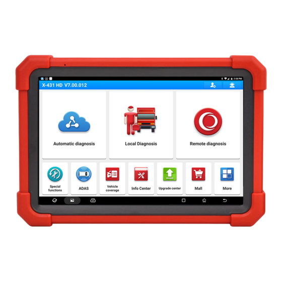
Launch X-431 PRO3 LINK Manual
Hide thumbs Also See for X-431 PRO3 LINK:
Table of Contents

Advertisement

Quick Links

LAUNCH
Copyright Information
Copyright © 2022 by LAUNCH TECH CO., LTD. All rights reserved. No part of this publication may be
reproduced, stored in a retrieval system, or transmitted in any form or by any means, electronic,
mechanical, photocopying, recording or otherwise, without the prior written permission of LAUNCH.
The information contained herein is designed only for the use of this unit. LAUNCH is not responsible
for any use of this information as applied to other units.
Important Safety Information
Warning: To avoid personal injury, property damage, or accidental damage to the product, read all of
the information in this section before using the product.
Work Area Safety
 Keep work area clean and well lit. Cluttered benches and dark areas may cause accidents.
 Do not connect or disconnect the tool while the ignition is on or the engine is running.
 DO NOT attempt to operate the tool while driving the vehicle. Have a second person to operate the
tool.
 Before testing a vehicle, put the transmission in PARK (for automatic transmission) or NEUTRAL (for
manual transmission). Engage the parking brake and chock the tires.
 NEVER smoke or allow a spark or flame in vicinity of battery or engine.
 The vehicle shall be tested in a well-ventilated work area, as engines produce various poisonous
compounds (hydrocarbon, carbon monoxide, nitrogen oxides, etc.)
 Do not operate the tool in explosive atmospheres, such as in the presence of flammable liquids,
gases, or heavy dust.
 Never leave the vehicle unattended while testing.
 Keep a fire extinguisher suitable for gasoline/chemical/electrical fires nearby.
 Use extreme caution when working around the ignition coil, distributor cap, ignition wires and spark
plugs. These components create hazardous voltages when the engine is running.
 Keep bystanders, children and visitors away while operating the tool.
 This product is not a toy. Do not allow children to play with or near this tool.
 Use as intended only. Do not modify.
 Inspect before every use; do not use if parts are loose or damaged.
 Do not place the tool on any unstable surface.
 Handle the tool with care. If the tool is dropped, check for breakage and any other conditions that
may affect its operation.
 Keep the tool dry, clean, free from oil, water or grease. Use a mild detergent on a clean cloth to clean
the outside of the tool when necessary.
 Store the tool and accessories in a locked area out of the reach of children.
 To avoid damaging the tool or generating false data, please make sure the vehicle battery is fully
charged and the connection to the vehicle DLC (Data Link Connector) is clear and secure.
 If the VCI (Vehicle Communication Interface) is not in use for a long period of time, it is suggested to
unplug the VCI from vehicle's DLC to conserve battery power.
Electrical Safety
 Do not use the tool while standing in water.
i

Advertisement

Table of Contents
loading
Need help?

Need help?

Do you have a question about the X-431 PRO3 LINK and is the answer not in the manual?

Questions and answers

Summary of Contents for Launch X-431 PRO3 LINK

  • Page 1 LAUNCH Copyright Information Copyright © 2022 by LAUNCH TECH CO., LTD. All rights reserved. No part of this publication may be reproduced, stored in a retrieval system, or transmitted in any form or by any means, electronic, mechanical, photocopying, recording or otherwise, without the prior written permission of LAUNCH.
  • Page 2 LAUNCH  Avoid body contact with grounded surfaces such as pipes, radiators, ranges and refrigerators.  Do not expose the tool or power adaptor to rain or wet conditions. Water entering the tool or power adaptor increases the risk of electric shock.
  • Page 3 - Connect the equipment into an outlet on a circuit different from that to which the receiver is connected. - Consult the dealer or an experienced radio/TV technician for help. X-431 PRO3 LINK (FCC ID: XUJX431PROV5) has been evaluated to meet general RF exposure requirement.
  • Page 4: Table Of Contents

    5.3 Remote Diagnose ........................23 5.3.1 Interface Layout ........................23 5.3.2 Add Friends ......................... 23 5.3.3 Start Instant Messaging ....................... 24 5.3.4 Launch Remote Diagnosis (Scanner-To-Scanner) .............. 25 5.3.5 Launch Remote Diagnosis (Scanner-To-PC) ..............26 5.4 Feedback ............................ 28 5.5 Diagnostic History ........................29 6 Service Function (Reset) ........................
  • Page 5 LAUNCH 6.7 Injector Coding (INJECTOR) ...................... 31 6.8 Battery Matching (BAT. RESET) ....................31 6.9 DPF Regeneration (DPF REG.) ....................31 6.10 Throttle Matching (ELEC. THROTTLE RLRN) ................. 31 6.11 Gearbox Matching (GEARBOX) ....................31 6.12 Headlight Matching (AFS RESET) ................... 32 6.13 Sunroof Initialization (SUNROOF) ....................
  • Page 6 LAUNCH 10 User Info ............................42 10.1 My Report ..........................42 10.2 VCI ............................42 10.3 VCI Management ........................42 10.4 Activate VCI ..........................42 10.5 Firmware Fix ..........................42 10.6 Sample ............................. 42 10.7 My Order ..........................42 10.8 Subscription Renewal Card ...................... 42 10.9 Profile ............................
  • Page 7: Introduction

    1 Introduction 1.1 Product Profile It inherits from LAUNCH’s advanced diagnosing technology and is characterized by covering a wide range of vehicles, featuring powerful functions, and providing precise test result. It has the following features: intelligent diagnose, local diagnose, SmartLink super remote diagnose, X-431 remote diagnose, service function, one-click update, diagnostic history, feedback, vehicle coverage lookup and ADAS calibration etc.
  • Page 8: Components & Controls

    LAUNCH Crossover cable x 1 Connects the SmartLink C device to the modem. Password envelope x 1 A piece of paper bearing the product Serial Number and Activation Code for product registration. Quick start guide x 1 Power adaptor x 1 + switching adaptor x 2 Charges the tablet via the AC outlet.
  • Page 9 LAUNCH 1. Microphone 2. Type-A USB Port • Connect to the SmartLink C device to perform vehicle diagnosis via the USB cable. • Connect to compatible add-on modules (such as Videoscope) or USB storage devices. 3. Type-C USB Port •...
  • Page 10: Smartlink C V2.0 Device

    LAUNCH Flip it out to any angle and work comfortable at your desk, or hang it on steering wheel. 1.3.2 SmartLink C V2.0 Device The SmartLink C V2.0 device features powerful functions and it can be applied in the following situations: 1).
  • Page 11: Technical Parameters

    LAUNCH Connect it to the modem via the crossover cable. It only applies to the SmartLink Super Remote Diagnostics. 4. DC-IN power jack It can obtain power via connecting the diagnostic cable to the vehicle’s DLC port or connecting to an external DC power supply.
  • Page 12: Initial Use

    LAUNCH 2 Initial Use 2.1 Charging & Turning On 1. Plug one end of the included charging port of the tablet, and the other end to the power adaptor. 2. Connect the other end to the AC outlet. appears on the screen, it indicates it is being charged. If the logo changes into , it indicates that the battery is fully charged.
  • Page 13: Wlan Setup

    2.6 WLAN Setup The tablet has built-in Wi-Fi that can be used to get online. Once you’re online, you can register the tool, surf the Internet, get apps, send email, launch the remote diagnosis, and check for software updates etc.
  • Page 14: Register & Update

    For initial use, the registration is the necessary first procedure to activate the tool. Tap the application icon on the home screen to launch it, and then tap Login on the upper right corner of the screen to enter the following screen.
  • Page 15: Job Menu

    LAUNCH Input the 12-digit Product Serial Number and 8-digit Activation Code (can be obtained from the password envelope), and then tap Activate. Tap Yes to navigate to the update center to update all available software. Tap No to ignore it. In this case, follow Chapter 8 to check for updates.
  • Page 16 To update vehicle diagnostic software and APK. This helps repair shops or mechanics to diagnose a remote vehicle, and Remote Diagnose launch instant messages, allowing for improved efficiency and faster repairs. Feedback To feed back the recent 20 diagnostic logs to us for issue analysis.
  • Page 17: Connections

    LAUNCH 4 Connections 4.1 Preparation 1. Make sure that the ignition is turned off and vehicle battery voltage range is 9-14V or 18-30V. 2. Find DLC location. For passenger cars, the DLC(Data Link Connector) is usually located 12 inches from the center of the instrument panel, under or around the driver’s side for most vehicles.
  • Page 18 LAUNCH 1. VCI 2. DB15F to HD15F data cable 3. HD15F to OBD16 adaptor 4. Vehicle’s DLC port For non-OBDII vehicles, refer to the above figure to make connection. 1. Select the appropriate adaptor according to the vehicle’s DLC port type (4).
  • Page 19: Diagnosis

    LAUNCH 5 Diagnosis 5.1 Intelligent Diagnose Through simple wireless communication between the display tablet and SmartLink C device, you can easily get the VIN (Vehicle Identification Number) information of the currently identified vehicle. Once the VIN is successfully decoded, the system will retrieve it from the remote server and then guide you to vehicle information page without the necessity of step-by-step manual menu selection.
  • Page 20 • Tap to launch the VIN recognition module. Place the VIN inside the viewfinder rectangle to scan it. The most recognizable location for this number is in the top left corner on the vehicle’s dashboard. Other locations include the driver’s door or post, and the firewall under the hood.
  • Page 21: Local Diagnose

    LAUNCH • Tap to input the VIN manually if the tablet has failed to decode the VIN of the vehicle. • Tap to scan the VIN barcode. If the VIN barcode cannot be recognized, please input the VIN manually. • Tap to scan the VIN character.
  • Page 22 LAUNCH In this case, Camera Scan and Enter VIN are available. Camera Scan: Scan the VIN automatically. Enter VIN: Input the vehicle VIN manually. If the tablet successfully identifies the vehicle model, it will directly enter the diagnostic function selection menu.
  • Page 23 LAUNCH 3). Select the desired test item to proceed. System Topology: Displays all available vehicle systems in form of topology structure. System List: Displays all available vehicle systems in form of list. ADAS Calibration: Performs ADAS calibration operations. It is extracted from the system list as a functional module and provides a quick access to ADAS system.
  • Page 24 LAUNCH • Report: Tap to save the current data in text format. All reports are saved in User Info -> My Report -> Health Reports. Notes: 1. Diagnostic report is classified into two categories: Pre-Repair report and Post-Repair report. To facilitate the comparison of the pre-repair and post-repair reports and get accurate test result, please make sure you saved the right type of the diagnostic report.
  • Page 25 LAUNCH System Scan: Tap to quickly scan which systems are installed on the vehicle. Select Detection: Select certain system manually to start scanning.  While in System List mode, the following screen will appear. • Enter: Select certain system, and tap this button to enter the diagnostic function selection screen.
  • Page 26 LAUNCH Help: Tap to view the help information. Code Search: Tap it to search for more information about the current DTC online. Report: To save the current data in text format. All reports are saved in User Info -> My Report ->...
  • Page 27 LAUNCH item with will be shown on the top of the selected data stream list. To remove it from the top of the list, just tap it again. B indicates this item will be displayed in Bold. A indicates this item will be displayed in Red.
  • Page 28 LAUNCH Report: To save the current data in text format. All reports are saved in User Info -> My Report -> Health Reports. Record: Tap to start recording diagnostic data. Recorded live data can serve as valuable information to help you in troubleshooting of vehicle problems. All recorded files are stored in User Info -> My Report ->...
  • Page 29: Remote Diagnose

    LAUNCH 5.3 Remote Diagnose This option aims to help repair shops or technicians launch instant messaging and remote diagnosis, making the repair job getting fixed faster. Tap Remote Diagnose on the Job menu, the screen appears blank by default. 5.3.1 Interface Layout Home button Tap it to navigate to the Job menu screen.
  • Page 30: Start Instant Messaging

    LAUNCH Here you can tap Remote Diagnose to launch remote diagnostics directly or choose to add the partner into the Contacts list. Tap the desired name from the list, the following screen will appear: Tap Add friend to send your request.
  • Page 31: Launch Remote Diagnosis (Scanner-To-Scanner)

    Remote Diagnose: To start a remote diagnostic session. Camera: Open camera to take pictures. Tap Clear to delete all the partner’s dialog logs. 5.3.4 Launch Remote Diagnosis (Scanner-To-Scanner) The tool is allowed to initiate remote diagnosis with other diagnostic tools, which are equipped with this module.
  • Page 32: Launch Remote Diagnosis (Scanner-To-Pc)

    Invite remote diagnostic assistant Wait for partner’s confirmation Start connecting after request confirmed Start Diagnosis Generate diagnostic report Cancel To cancel this operation. 5.3.5 Launch Remote Diagnosis (Scanner-To-PC) User also can ask for remote control from a PC client technician.
  • Page 33 LAUNCH Slide the switch to ON Notify the partner of the remote diagnostic web link Input the partner’s official account and password Input the Serial Number of your handset Start Diagnosis Generate diagnostic report Tap Remote, the following screen will appear: 1.
  • Page 34: Feedback

    LAUNCH 3. Tell the partner to input his own official technician account and password, and then tap Login to navigate to the following figure. 4. Tell the partner to check the box Serial number and enter the Serial Number provided by you, and then tap Start remote diagnosis to control your device remotely.
  • Page 35: Diagnostic History

    LAUNCH to the remote server automatically once the tablet gets the stable network. 5.5 Diagnostic History This function enables users to directly get access to the previously tested vehicle’s diagnostic records in details, so users can resume from the last operation, without starting from scratch.
  • Page 36: Service Function (Reset)

    LAUNCH 6 Service Function (Reset) It offers coding, reset, relearn and more service functions, to help vehicles get back to functional status after repair or replacement. Available tests vary by vehicle manufacturer, year, and model. Due to continuing improvements, the available service functions are subject to change at any time. To enjoy more service functions, you are suggested to check for updates on a regular basis.
  • Page 37: Anti-Theft Matching (Immo)

    LAUNCH (MIL). It needs to be performed in the following cases: 1. After the engine ECU, crankshaft position sensor, or crankshaft flywheel is replaced. 2. The DTC “tooth not learned” is present. 6.6 Anti-theft Matching (IMMO) This function can match the anti-theft key after replacing the ignition key, ignition switch, instrument cluster, engine control unit (ECU), body control module (BCM), and remote control battery.
  • Page 38: Headlight Matching (Afs Reset)

    LAUNCH It needs to be performed in the following cases: When the gearbox is disassembled or repaired. 6.12 Headlight Matching (AFS RESET) This function enables you to initialize the adaptive headlamp system. 6.13 Sunroof Initialization (SUNROOF) This function enables you to set the sunroof lock off, closed when it rains, sliding / tilting sunroof memory function, temperature threshold outside the car etc.
  • Page 39: High Voltage Battery Detection (High Voltage Battery)

    LAUNCH 6.22 High Voltage Battery Detection (HIGH VOLTAGE BATTERY) This function is used for high voltage battery diagnosis and status information detection. 6.23 Windows Calibration This function is used to perform door window matching to recover the ECU initial memory, and recover the automatic ascending and descending function of power window.
  • Page 40: Immo Programming

    LAUNCH 6.33 IMMO Programming This function enables you to perform read-write function for vehicle key, EEPROM, MCU, and EEPROM/FLASH data of vehicle engine/gearbox ECU.
  • Page 41: Smartlink Diag

    LAUNCH 7 SmartLink Diag. SmartLink is a newly developed powerful service system dedicated to remote vehicle diagnosis and service. In the SmartLink ecology system, if a technician (SmartLink C) does not have time to puzzle through a touch vehicle problem, he can seek a trusted second opinion or additional expertise on various vehicle issues from remote master technicians or repair shops (SmartLink B).
  • Page 42 LAUNCH • SmartLink Service Platform – It can be accessed from the SmartLink module of the diagnostic tablet. There are two modules available on the link service platform: Common user (for SmartLink C) and Service provider (for SmartLink B). • SmartLink C (Customer) - SmartLink Service Subscriber. In the SmartLink system, the...
  • Page 43 • SmartLink B (Business) - SmartLink Service Provider. In the SmartLink system, the SmartLink B needs to perform the following operations. 1). Launch Service Link Platform: Binds SmartLink B dongles and accepts orders from SmartLink C. • If the SmartLink B dongle works with the LAUNCH-specific diagnostic tool equipped with SmartLink module, tap SmartLink to add the SmartLink B device and accepts orders on the diagnostic tool.
  • Page 44: Software Update

    LAUNCH 8 Software Update This module enables you to update the diagnostic software & App and frequently used software. 8.1 Update Diagnostic Software & APP Go to Software Update on the Job Menu and tap the Downloaded tab. The Available tab displays a list of software that can be updated. Under it, all software is categorized into three kinds: •...
  • Page 45: Renew Subscription

    LAUNCH Tap Update to start downloading. Once download is finished, the software packages will be installed automatically. 8.3 Renew Subscription If the software subscription is due or expires, the system will prompt you to renew your subscription. Tap Renewal to open the Mall, and then follow the on-screen prompts to finish the subscription.
  • Page 46: Add-On Modules (Toolbox)

    LAUNCH 9 Add-on Modules (Toolbox) 9.1 ADAS (Calibration) This module enables you to effectively and accurately calibrate a wide range of camera-based & radar-based driver assistance systems, e.g. the front camera for the lane departure warning system, the radar sensor for the ACC (Adaptive Cruise Control) or the camera for adaptive headlights. It needs to work with the specific ADAS calibration tool (sold separately).
  • Page 47: Oscilloscope (Optional)

    LAUNCH 9.8 Oscilloscope (Optional) This module can make the auto repair technician quickly judge the faults on automotive electronic equipment and wiring. For more details, please refer to the User Manual included with the module.
  • Page 48: User Info

    LAUNCH 10 User Info This function allows users to manage personal information and VCI. 10.1 My Report This option is used to view, delete or share the saved reports. Tap Report, there are total 3 options available. In case the DTC result is saved on Read Trouble Code page, the files will be listed under Health Reports tab.
  • Page 49: Profile

    This option is designed to establish a wireless connection between the tablet and the Wi-Fi printer (sold separately) while performing printing operations. The App is compatible with the LAUNCH Wi-Fi Printer (sold separately) and System (external printer). For LAUNCH Wi-Fi printer, follow the User Manual included with the printer to configure it.
  • Page 50: Clear Cache

    LAUNCH 5. Select All Printers -> Add printer and enable the installed printer service, the system starts searching for all available Wi-Fi printers of the brand. 6. Select the desired Wi-Fi printer from the list. If the chosen Wi-Fi printer hotspot is open, the tablet can connect it directly.
  • Page 51 LAUNCH There are two types of sub-accounts: one is existing account and the other is newly created account. The main account has the functions of adding and removing sub-accounts, the sub-account can also be unbound from the main account. Tap Device account management, the following screen will appear: Tap Add sub account, the following popup will appear: •...
  • Page 52: Login/Logout

    LAUNCH 10.11.8 Login/Logout To logout the current user ID, tap Logout. To login the system again, tap Login. 10.12 Diagnostic Software Clear This item allows you to hide/clear the diagnostic software that is not frequently used. Note: Removing software may completely delete the software from the tablet. If some software is not used and...
  • Page 53: J2534 Reprogramming

    Except that the SmartLink C acts as a VCI device and a SmartLink dongle, it also can be used as a J2534 PassThru device, working together with the PC installed with the OEM diagnostic software to perform the J2534 reprogramming. In this case, the PC needs to install with the LAUNCH's J2534 tool, which can be downloaded from www.cnlaunch.com.
  • Page 54: Synchronization

    LAUNCH 12 Synchronization You can transfer media files, screenshots and APK between the PC and tablet. 1. Connect one end of the included charging/data cable to the charging/data I/O port of the tablet, and the other end to the USB port of the PC.
  • Page 55: Faq

    After the tablet has been successfully reset, follow the steps below to download the App: 1. Launch the browser and the default official Launch website opens (If a blank page pops up, just type in www.x431.com in the input bar).
  • Page 56: About Smartlink Diag

    7. How to retrieve the login password? Please follow below steps to proceed in case you forgot the login password: 1. Tap the application icon on the home screen to launch it. 2. Tap Login on the upper right corner of the screen.
  • Page 57 LAUNCH 5. Is it necessary to re-ignite the car after the diagnostic system starts working? For the sake of some vehicle's conditions, the re-ignition will provide you a more detailed analysis after OBD diagnosis.
  • Page 58: Glossary Of Terms & Abbreviations

    LAUNCH 14 Glossary of Terms & Abbreviations ABS – Anti-Lock Brake System AC – Alternative Current ADAS -- Advanced Driver Assistance Systems AFS – Adaptive Front-lighting System CAN – Controller Area Network Communication Protocol – Allows different systems and sensors in a vehicle to communicate.
  • Page 59 LAUNCH LED – Light Emitting Diode Manufacturer Specific Code – A DTC that applies only to OBD II-compliant vehicles made by a specific manufacturer. MIL – Malfunction Indicator Lamp The vehicle’s “Check Engine” warning light that activates when a DTC is stored.
  • Page 60 The exclusive remedy for any automotive meter found to be defective is repair or replacement, and LAUNCH shall not be liable for any consequential or incidental damages.
  • Page 61 Statement: LAUNCH reserves the rights to make any change to product designs and specifications without notice. The actual object may differ a little from the descriptions in the manual in physical appearance, color and configuration. We have tried our best to make the descriptions and illustrations in the manual as...

This manual is also suitable for:

Smartlink c v2.0

Table of Contents