
Related Manuals for ZKTeco C2-260


Summary of Contents for ZKTeco C2-260
- Page 1 Quick Start Guide C2-260/inBio2-260 Access Controller Version: 1.1 Due to regular upgrades of systems and products, ZKTeco could not guarantee exact consistency between the actual product and the written information in this manual.
-
Page 2: What's In The Box
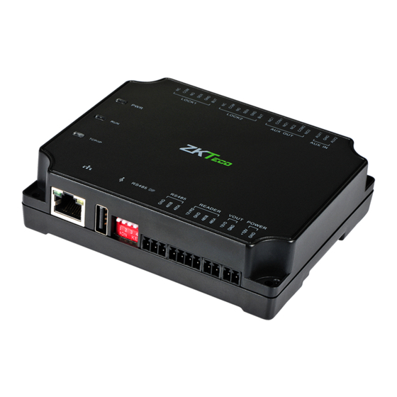
What’s in the Box LOCK1 LOCK2 AUX OUT AUX IN TCP/IP RS485 READER VOUT POWER RS485 DIP C2-260 / inBio2-260 4 Screws & Anchors 2 Screwdrivers 4 Diodes... -
Page 3: Safety Precautions
Safety Precautions The following precautions are to ensure user's safety and prevent any damage. Please read the instructions carefully before installation. Do not expose to direct sunlight, water, dust and soot. Do not place any magnetic objects near the product. Magnetic objects such as magnets, CRT, T V, monitors or speakers may damage the device. -
Page 4: Product Pin Diagram
Product PIN Diagram 2 Lock & Door Sensor 2 Aux Output 2 Aux Input LOCK1 LOCK2 AUX OUT AUX IN TCP/IP RS485 READER VOUT POWER RS485 DIP Figure 1... -
Page 5: Led Indicators
LED Indicators LINK Solid Green LED indicates TCP/IP com- munication is normal. LOCK1 LOCK2 LOCK1 LOCK2 Flashing (ACT )Yellow LED indicates data LOCK1 LOCK2 communication is in progress. Figure 2 Solid (POWER) Red LED indicates the panel is powered on. Figure 3 Slowly ashing Green LED indicates normal... -
Page 6: Panel Installation
Panel Installation Wall Mounting LOCK1 LOCK2 AUX OUT AUX IN TCP/IP RS485 READER VOUT POWER RS485 DIP Step 1 Step 2 Drill holes on the wall Fix the device with four screws Figure 6 Rail Mounting Step 1 Step 2 Fix the guide rail on the wall Fix the device to the rail mounting. - Page 7 Panel Installation Normally Close Lock Normally Open Lock Exit Button IR Sensor Floodlight Detector LOCK1 LOCK2 AUX OUT AUX IN TCP/IP RS485 READER VOUT POWER RS485 DIP Ethernet Cable 485 Convertor RS485 Reader 12V DC Power Supply Figure 8 The auxiliary input may be connected to infrared body detectors, re alarms, or smoke detectors. The auxiliary output may be connected to alarms, cameras or door bells, etc.
-
Page 8: Installation Diagram
Installation Diagram Ethernet Communication wire RS485 Communication wire 220/110 V Input C2-260/inBio2-260 Access Control Bundle CEILING Sensor Electric Lock Exit Button Outdoor RS485 reader Indoor RS485 reader OUTDOOR INDOOR Figure 9... - Page 9 (inBio2-260) Note: 1. It’s recommended to connect maximum four readers to one C2-260/inBio2-260. 2. A single RS485 reader interface can supply a maximum of 750 mA (12V) current. So the entire current consumption should be less than this max value when the readers share the power with the panel.
- Page 10 AUX IN C2-260 / inBio2-260 TCP/IP RS485 READER VOUT POWER RS485 DIP DC12V 485A 485B Router DM10 DM10 DC12V DC12V Note: 1. A C2-260/inBio2-260 can connect to maximum eight DM10 modules.. 2. Each DM10 module requires a separate power supply.
- Page 11 Router DC12V DC12V Input Input Device Device AUX485 AUX485 Note: 1. A C2-260/inBio2-260 can connect to maximum two AUX485 modules. 2. Each AUX485 module can connect to maximum four auxiliary devices. 3. Each AUX485 module requires a separate power supply.
- Page 12 Connection with WR485 LOCK1 LOCK2 AUX OUT AUX IN C2-260 / inBio2-260 TCP/IP RS485 READER VOUT POWER RS485 DIP DC12V 485A 485B Router +12V WR485 WR485 Note: 1. A C2-260/inBio2-260 can connect to maximum four WR485 modules.
- Page 13 Connection to ZKBioAccess Software Here the connection between C2-260/inBio2-260 and AUX485 is used as an example to illustrate the software settings. After proper wiring, perform the following steps: 1. Set the RS485 address of AUX485 from 1-15. 2. Inclusion of C2-260/inBio2-260 to software: Open the ZKBioAccess Software.
- Page 14 4. Click [Device] > [Auxiliary Input] to view all the auxiliary inputs. Note: For other speci c operations, please refer to ZKBioAccess User Manual.
-
Page 15: Speci Cations
Speci cations Model C2-260 Number of Doors Supported by Default Number of Auxiliary Inputs Number of Auxiliary Outputs RS485 Extension Port RS485 Reader Port Number of Readers Supported Types of Readers Supported RS485 card reader, Wiegand reader (WR485) DM10 (Single-Door Extension Board) (Optional) Max. - Page 16 ZKTeco Industrial Park, No. 26, 188 Industrial Road, Tangxia Town, Dongguan, China. Phone : +86769-82109991 Fax : +86755-89602394 www.zkteco.com Copyright © 2020 ZKTECO CO., LTD. All Rights Reserved.
Need help?
Do you have a question about the C2-260 and is the answer not in the manual?
Questions and answers