Advertisement

USER MANUAL
C5S110&120&140
Version: 1.1
Date: Apr., 2018

Advertisement

Table of Contents
loading

Summary of Contents for ZKTeco C5S120

  • Page 1 USER MANUAL C5S110&120&140 Version: 1.1 Date: Apr., 2018...
  • Page 2 About This Manual This manual introduces C5S110/120/140 access control panel installation connection and user instructions.
  • Page 3: Table Of Contents

    Contents 1 Safety Instructions ....................................... 1 1.1 Important Security Instructions ................................1 1.2 Installation Cautions ....................................3 2 System Introduction ......................................4 2.1 System Function Parameters ................................4 2.2 Product Technical Parameters................................4 2.3 
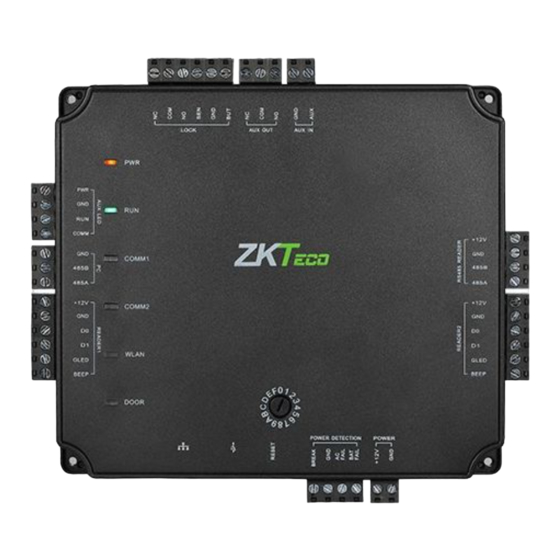
Control Panel Indicators ..................................4 3 Installation and Connection ....................................6 3.1 Chassis Installation ....................................
  • Page 4: Safety Instructions

    1 Safety Instructions 1.1 Important Security Instructions 1) Read, follow and keep instructions: Before operating the equipment, read and follow strictly all security and operation instructions. Please keep the instructions in good condition for future reference. 2) Accessories: Please use the accessories recommended by the manufacturer or delivered with the product. Any other related product is not recommended as the major alarming or monitoring system.
  • Page 5 Violation of any of the following cautions is likely to lead to personal injury or equipment failure, We will not be responsible for the damages or injuries caused thereby.  Before installation, switch off the external circuit (that supplies power to the system), including locks. ...
  • Page 6: Installation Cautions

    1.2 Installation Cautions The conduits of wires under relay must be matched with metaled conduits, other wires can use PVC conduits, to prevent failure caused by rodent damage. Although a control panel is designed with good antistatic, lightning-proof, and leakage-proof functions, ensure its chassis and the AC ground wire are connected properly and the AC ground wire is grounded physically.
  • Page 7: System Introduction

    High-speed 32-bit 1.2GHz CPU, 128M RAM, and 256M Flash. Embedded LINUX operating system. The C5S110 for one-door one-way/two-way, C5S120 for two-door one-way/two-way, and C5S140 for two-door two-way or four door one-way/two-way A maximum of 100,000 card holders and 200,000 offline event records.
  • Page 8 3) WLAN indicator (green): flashing indicates the system is communicating in wireless (WIFI) mode. 4) DOOR indicator (green): flashing indicates a door opening signal (a door is opened). Diagram of C5S140 indicators: System Introduction 5...
  • Page 9: Installation And Connection

    3 Installation and Connection 3.1 Chassis Installation  The following describes the chassis installation process: If the provided chassis is used, the control panel has been installed inside the chassis by default. Fix the chassis on the wall, remove the hole plug or get through the thread hole, connect the access control cable, and install other components.
  • Page 10: Installation Of Access Control Panel Wires

    3.2 Installation of Access Control Panel Wires +12V power line TCP/IP network communication wire or PoE line (for PoE only) RS485 network communication wire Wireless network (WIFI) communication Ceiling Control Panel Door sensor Electronic lock Exit button Outdoor Indoor reader reader Indoor Outdoor...
  • Page 11: Control Panel System Installation

     Note: Despite the preceding example of four-door one-way/two-way, C5S140 also can be connected to two-door two-way. C5S110 can be connected to one-door one-way/two-way at most, and C5S120 can be connected to two-door one-way/two-way. The access control management system consists of two parts: management workstation (PC) and control panel.
  • Page 12: Control Panel Connection Terminals

    The management workstation and control panel communicate through TCP/IP, RS485, and wireless network (WIFI). On a single RS485 bus, each management workstation can be connected to a maximum of 16 C5S control panels (with a maximum of 16 bits of DIP switch, a maximum of 16 device numbers can be set). The communication wires should be kept away from high-voltage wires as far as possible, and should be neither routed in parallel with nor bundled with power wires.
  • Page 13 C5S120 terminal connection diagram State Indicator #1 Door #2 Door Antenna Connector EXT RS485 Wiegand Reader 3 Wiegand Reader 1 Wiegand Reader 2 Wiegand Reader 4 Rotary DIP Switch 10 C5S110&120&140 User Manual...
  • Page 14 C5S140 terminal connection diagram State Indicator #1 Door #2 Door #3 Door #4 Door Antenna Connector EXT RS485 Wiegand Reader 3 Wiegand Reader 1 Wiegand Reader 4 Wiegand Reader 2 Rotary DIP Switch Descriptions of the terminals: 1) The auxiliary input may be connected to infrared body detectors, fire alarms, or smoke detectors. 2) The auxiliary output may be connected to alarms, cameras or door bells, etc.
  • Page 15: Connection With Door Sensors, Exit Switches, And Auxiliary Input Devices

    Ports on the C5S Series control panel: C5S110 C5S120 C5S140 Functional Port (One-Door (Two-Door (Four-Door One-Way/Two-Door Two-Way) Two-Way) Two Way) Wiegand reader interface Exit button Control lock relay Door sensor Auxiliary Input Auxiliary Output RS485 reader RS485 & PC communication √...
  • Page 16: Connection With Readers

    and its connection is correct and secure. (Cut off the exposed end of any unused wire and wrap it with insulating tape.) Note to guard against electromagnetic interference (such as light switches and computers). It is recommended to use two-core wires with a gauge over 0.3mm as the connection wire between an exit switch and a control panel.
  • Page 17 RS485 reader). 1) Connection with RS485 Readers C5S110 can connect two RS485 readers in the one-door two-way mode. C5S120 provides four readers, which can be connected in the two-door two-way mode. C5S140 provides eight readers, which can be connected in the four-door two-way mode.
  • Page 18: Relay Output Connection

    3.7 Relay Output Connection C5S110 has two relays (one used as a control lock by default, and the other used as an auxiliary output); C5S120 has three relays (two used as control locks by default, and the other one used as auxiliary outputs); C5S140 has five relays (four used as control locks by default, and the other one used as auxiliary outputs).
  • Page 19 3) Our access control panel is powered by standard PoE or access control power. You can choose either of the two power supplies as needed. The two power supplies provide 12V/3A power for only the power consumption of the control panel, Wiegand readers, and output power consumption of RS485 reader. 4) To protect the access control system against the self-induced electromotive force generated by an electronic lock at the instant of switching off/on, it is necessary to connect a diode in parallel (please use the FR107 delivered with the system) with the electronic lock to release the self-induced electromotive...
  • Page 20: Access Control Panel System Power Supply Structure

    3.8 Access Control Panel System Power Supply Structure Access Control Panel System Power Supply PoE System Installation and Connection 17...
  • Page 21 The C5S access control panel is powered through a +12 V DC power supply or PoE, whichever can be chosen. If you choose a +12 V DC power supply, generally, to reduce power interference between control panels, each control panel should be powered separately. If you choose PoE, the TCP/IP network interface of the access control panel can serve as a PoE interface and a PC communication interface.
  • Page 22: Equipment Communication

    4 Equipment Communication The background PC software is able to communicate with the system according to three protocols (TCP/IP, RS485 and WIFI) for data exchange and remote management. 4.1 Access Control Networking Wires and Wiring 1) RS485 communication wires are made of internationally accepted shielded twisted pairs (RVVSP), which prove effective to prevent and shield interference.
  • Page 23: Tcp/Ip Communication

    4.2 TCP/IP Communication The Ethernet 10/100Base-T Crossover Cable, a type of crossover network cable, is mainly used for cascade hubs and switches, or used to connect two Ethernet end-points directly (without a hub). Both 10Base-T and 100Base-T are supported. Printer Card Issuer Switch TCP/IP...
  • Page 24: Wireless Communication

    4.4 Wireless Communication 1) Create a valid connection string using TCP/IP, and make sure that there is available WiFi network. 2) Input the IP address of the controller (factory default is 192.168.1.201) in the address bar; enter the user name and password (both are admin), and click [Sign In] to access the ZKPanelWeb.
  • Page 25 5) Select available WiFi in the wireless network list and click [Action] (Figure 1), enter the key, and configure DHCP (the IP address and gateway must be in the same network segment as the wireless network IP address), and then click [Confirm]. After the connection is successful, the wireless connection status shows connected (as shown in Figure 2), and the device's WLAN indicator turns green.
  • Page 26: Dip Switch Settings

     Remarks:  You must add the C5S control panel to the software through TCP/IP before setting WIFI parameters. Connection through RS485 is not allowed.  Connect the PC with the software installed to the router and set the same network segment to allow the control panel to communicate with the PC and background software through WIFI.

This manual is also suitable for:

C5s110C5s140

Table of Contents