Table of Contents
Advertisement
Quick Links
Advertisement
Table of Contents

Related Manuals for Fluidwell F093-P


Summary of Contents for Fluidwell F093-P
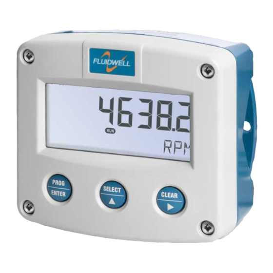
- Page 1 TACHOMETER MONITOR ENGINE SPEED AND RUNNING HOURS WITH ALARM OUTPUT Signal input Tachometer: pulse, Namur and coil Alarm output: alarm on RPM and running hours Options: Intrinsically Safe F-Series - Field mounted indicators for safe and hazardous areas. More info: www.fluidwell.com/fseries...
-
Page 2: Safety Instructions
Compatibility). Do connect a proper grounding to the aluminum casing as indicated if the F093-P has been supplied with the 115-230V AC power-supply type PM. The green / yellow wire between the back-casing and removable terminal-block may never be removed. -
Page 3: About The Operation Manual
This operation manual describes the standard unit as well as most of the options available. For additional information, please contact your supplier. A hazardous situation may occur if the F093-P is not used for the purpose it was designed for or is used incorrectly. Please carefully note the information in this operating manual indicated by the pictograms: A "warning"... -
Page 4: Table Of Contents
Safety rules and precautionary measures ..................... 2 About the operation manual ........................3 Contents manual ............................ 4 Introduction ..........................5 1.1. System description of the F093-P ................5 Operational ..........................6 2.1. General ........................6 2.2. Control panel ........................ 6 2.3. -
Page 5: Introduction
Fig. 1: Typical application for the F093-P. Configuration of the unit The F093-P has been designed to be implemented in many types of applications. For that reason, a SETUP-level is available to configure your F093-P according to your specific requirements. -
Page 6: Operational
Take careful notice of the " Safety rules, instructions and precautionary measures " in the front of this manual. This chapter describes the daily use of the F093-P. This instruction is meant for users / operators. 2.2. CONTROL PANEL The following keys are available: Fig. -
Page 7: Operator Information And Functions
CLEAR or wait for 20 seconds. Re-initialization of running hours DOES NOT influence the accumulated running hours. Note: If pressing CLEAR twice does not clear the running hours, the F093-P is configured not to allow this in Operation mode. - Page 8 The remaining lifetime after the first moment of indication is generally several days up to some weeks. LOW BATTERY Fig. 5: Example of low-battery alarm. • Alarm 01-03 When "alarm" is displayed, please consult Appendix B: problem solving. FW-F093-P-MAN-EN_v0101_01...
-
Page 9: Configuration
Operating Manual before carrying out its instructions. The F093-P may only be operated by personnel who are authorized and trained by the operator of the facility. All instructions in this manual are to be observed. - Page 10 After selecting a sub-function, the next main function is selected by scrolling through all "active" sub- functions (e.g. 1, 11, 12, 13, 14, 1, 2, 3, 31 etc.). The “CLEAR” button can be used to jump a step back if you missed the desired function. FW-F093-P-MAN-EN_v0101_01...
- Page 11 Note: alterations will only be set after ENTER has been pressed! To return to OPERATOR-level: In order to return to the operator level, PROG will have to be pressed for three seconds. Also, when no keys are pressed for 2 minutes, SETUP will be left automatically. FW-F093-P-MAN-EN_v0101_01...
-
Page 12: Overview Functions Setup Level
- shelf SENSOR SIGNAL npn - npn_lp - reed - reed_lp - pnp - pnp_lp - namur - coil_hi - coil_lo - active OTHERS TYPE / MODEL F093-P SOFTWARE VERSION 03.xx.xx SERIAL NO. xxxxxxx PASS CODE 0000 - 9999... -
Page 13: Explanation Of Setup-Functions
(important for battery powered applications). Note: for low frequency applications (below 10Hz): do not program more than 10 pulses else the update time will be very slow. Note: for high frequency application (above 1kHz) do program a value of 100 or more pulses. FW-F093-P-MAN-EN_v0101_01... -
Page 14: Alarm
RPM and HOURS, at “TOGGLE” it will automatically swap every 3 seconds between RPM and HOURS and with “HAND” you can manually set the display you prefer. The following can be selected: ALL – TOGGLE – HAND FW-F093-P-MAN-EN_v0101_01... -
Page 15: Power Management
When used with the internal battery option, the user can expect reliable measurement over a long period of time. The F093-P has several smart power management functions to extend the battery life time significantly. Two of these functions can be set:... -
Page 16: Sensor
To wake up the unit again, press the SELECT-key twice. 6 - SENSOR The F093-P is able to handle several types of input signal. The type of SIGNAL Tachometer pickup / signal is selected with SETUP 61. -
Page 17: Installation
Operating Manual before carrying out its instructions. The F093-P may only be operated by personnel who are authorized and trained by the operator of the facility. All instructions in this manual are to be observed. -
Page 18: Dimensions- Enclosure
1/2"NPT M20 x 1,5 0.12" 0.12" M20 x 1,5 3x 1/2"NPT 25mm 25mm 15 15 M20 x 1,5 M20 x 1,5 4x M20 x 1,5 29.1 mm (1.15”) 115 mm (4.53”) 31 mm (1.22”) Fig. 6: Dimensions Aluminum enclosures. FW-F093-P-MAN-EN_v0101_01... - Page 19 118 mm (4.65”) 25mm 25mm D=20mm D=20mm 12mm 12mm 30mm 30mm 24mm 24mm D=12mm D=16mm D=16mm D=20mm 36mm 36mm 0.12” 0.12” D=22mm (0.866") 3x D=22mm (0.866”) 29.1 mm (1.15”) 115 mm (4.53”) 31 mm (1.22”) Fig. 7: Dimensions GRP enclosures. FW-F093-P-MAN-EN_v0101_01...
-
Page 20: Installing The Hardware
• This unit must be installed in accordance with the EMC guidelines (Electro Magnetic Compatibility). • Do ground the aluminum casing properly as indicated, if the F093-P has been supplied with the 115-230V AC power-supply type PM. The green / yellow wire between the back-casing and removable terminal-block may never be removed. -
Page 21: Terminal Connectors With Power Supply - Type : Pb / Pd / Px
The screen of the signal wire must be connected to the common ground terminal The input signal type has to be selected with the correct SETUP-function (read par. 3.2.3.) The F093-P is suitable for use with Tachometers which have a coil output signal. Two sensitivity levels can be selected with the SETUP-function: COIL LO: sensitivity from about 90mVp-p. - Page 22 Page 22 Pulse-signal NPN / NPN-LP: The F093-P is suitable for use with Tachometers which have a NPN output signal. For reliable pulse detection, the pulse amplitude has to go below 1.2V. Signal setting NPN-LP employs a low-pass signal noise filter, which limits the maximum input frequency - read par. 3.2.3.
- Page 23 Common ground unit NAMUR-signal: The F093-P is suitable for Tachometers with an Namur signal. The standard F093-P is not able to power the Namur sensor, as an external power supply for the sensor is required. However, a 8.2V sensor supply voltage (terminal 6) can be provided with type PD.
-
Page 24: Terminal Connectors With Power Supply - Type : Pf / Pm
For Intrinsically Safe applications: read chapter 5. The following terminal connectors are available: POWER SUPPLY ALARM OUTPUT SENSOR SIGNAL TYPE: TYPE: TYPE: P: PF / PM OA-OR-OT PULSE INPUT SIGNAL Fig. 10: Overview of terminal connectors F093-P-(PF / PM) and options. FW-F093-P-MAN-EN_v0101_01... - Page 25 1.2, 3.2, 8.2, 12, 24V max. 400mA@24V DC PM 115-230V AC ± 10% 1.2, 3.2, 8.2, 12, 24V max. 400mA@24V DC EARTH Note PF / PM The running hours consumption of the sensor, transistor output type OA and backlight type ZB may not exceed 400mA@24V DC. FW-F093-P-MAN-EN_v0101_01...
- Page 26 The input signal type has to be selected with the correct SETUP-function (read par. 3.2.3.) Coil-signal: The F093-P is suitable for use with Tachometers which have a coil output signal. Two sensitivity levels can be selected with the SETUP-function: COIL LO: sensitivity from about 90mVp-p.
- Page 27 Common ground unit Pulse-signal NPN / NPN-LP: The F093-P is suitable for use with Tachometers which have a NPN output signal. For reliable pulse detection, the pulse amplitude has to go below 1.2V. Signal setting NPN-LP employs a low-pass signal noise filter, which limits the maximum input frequency - read par. 3.2.3.
- Page 28 Common ground unit Reed-switch: The F093-P is suitable for use with Tachometers which have a reed-switch. To avoid pulse bounce from the reed-switch, it is advised to select REED LP - low-pass filter (read par. 3.2.3.) Reed - switch signal input...
-
Page 29: Intrinsically Safe Applications
Safety Instructions Certificates, safety values, control drawing and declaration of compliance can be found in the document named: “Fluidwell F0..-P-XI - Documentation for Intrinsic Safety”. For installation under ATEX directive: this intrinsically safe device must be installed in accordance with the Atex directive 94/9/EC and the product certificate KEMA 05ATEX1168 X. -
Page 30: Terminal Connectors Intrinsically Safe Applications
FWCD-0003. Tamb CSA Certificate nr: CSA.08.2059461 – FM Project ID: 3033306 -40°C ... +70°C Made in Veghel, The Netherlands by Fluidwell bv -40°F ... +158°F KEMA 05ATEX1168 X Battery powered applications: II 1 G Ex ia IIC T4 Replace with certified II 1 D Ex iaD 20 IP 65 / 67 T 100°C... -
Page 31: Configuration Examples Intrinsically Safe Applications
PX will power the unit; the battery will be disabled automatically till power is disconnected. Fig. 15: Configuration example Intrinsically Safe. Configuration example no. 2 Configuration example IIA - IIB and IIC application - F093-P-OT-PX-XI-(ZB) HAZARDOUS AREA SAFE AREA TERMINAL CONNECTORS... - Page 32 Page 32 Configuration example no. 3 Configuration example IIA - IIB and IIC application - F093-P-OT-PX-XI-ZB HAZARDOUS AREA SAFE AREA TERMINAL CONNECTORS F0-series = max. 30 V Power supply Supply backlight = max. 200 mA Backlight option: type ZB For example = max.
-
Page 33: Battery Replacement Instructions
Page 33 5.4. BATTERY REPLACEMENT INSTRUCTIONS FW-LiBAT-001 - INST001 Fig. 19: Battery replacement instructions Intrinsically Safe Battery. FW-F093-P-MAN-EN_v0101_01... -
Page 34: Maintenance
Operating Manual before carrying out its instructions. The F093-P may only be operated by personnel who are authorized and trained by the operator of the facility. All instructions in this manual are to be observed. -
Page 35: Appendix A: Technical Specification
20-30V DC. Power consumption max. 1 Watt. Note: with type PF / PM: internally powered. Note PF / PM The running hours consumption of the sensor, active output type OA and backlight type ZB may not exceed 400mA@24V DC. Note I.S. application for intrinsically safe applications, consult the safety values in the certificate. FW-F093-P-MAN-EN_v0101_01... - Page 36 One passive transistor output - not isolated. Load max. 50V DC - 300mA. Type OA One active 24V DC transistor output; max. 400mA per output (requires type PF or PM). Type OR One mechanic relay output; max. switch power 230V AC - 0,5A (requires type PF or PM). FW-F093-P-MAN-EN_v0101_01...
- Page 37 7 digits. Units According to selection for engine speed/running hours. Decimals According to selection for engine speed/running hours. Type of alarm Low and/or high engine speed alarm and/or running hours alarm.. Includes delay time alarm and configurable alarm output. FW-F093-P-MAN-EN_v0101_01...
-
Page 38: Appendix B: Problem Solving
Page 38 APPENDIX B: PROBLEM SOLVING In this appendix, several problems are included that can occur when the F093-P is going to be installed or while it is in operation. Tachometer does not generate pulses: Check: Signal selection SETUP - 61, ... -
Page 39: Index Of This Manual
Fig. 8: Grounding aluminum enclosure with option PM 115-230V AC..........20 Fig. 9: Overview of terminal connectors F093-P-(PB / PD / PX) and options........21 Fig. 10: Overview of terminal connectors F093-P-(PF / PM) and options......... 24 Fig. - Page 40 _ _ _ _ _ _ _ 74 pass code 0000 75 tagnumber 0000000 Fluidwell bv FW-F093-P-MAN-EN_v0101_01 PO box 6 Voltaweg 23 Website: www.fluidwell.com 5460 AA Veghel 5466 AZ Veghel Find your nearest representative: www.fluidwell.com/representatives The Netherlands The Netherlands Copyright Fluidwell bv - 2013 - FW-F093-P-MAN-EN_v0101_01...
Need help?
Do you have a question about the F093-P and is the answer not in the manual?
Questions and answers