
Related Manuals for Fluidwell F012-A


Summary of Contents for Fluidwell F012-A
- Page 1 F012-A FLOWRATE INDICATOR / TOTALIZER Signal input flowmeter: (0)4-20mA. Options: Intrinsically Safe. F-Series - Field mounted indicators for safe and hazardous areas. More info: www.fluidwell.com/fseries...
-
Page 2: Safety Instructions
Compatibility). Do connect a proper grounding to the aluminum casing as indicated if the F012-A has been supplied with the 115-230V AC power-supply type PM. The green / yellow wire between the back-casing and removable terminal-block may never be removed. -
Page 3: About The Operation Manual
This operation manual describes the standard unit as well as most of the options available. For additional information, please contact your supplier. A hazardous situation may occur if the F012-A is not used for the purpose it was designed for or is used incorrectly. Please carefully note the information in this operating manual indicated by the pictograms: A "warning"... -
Page 4: Table Of Contents
Safety rules and precautionary measures ....................... 2 About the operation manual ..........................3 Contents manual .............................. 4 Introduction ..........................5 1.1. System description of the F012-A ..................5 Operational ..........................6 2.1. General ..........................6 ... -
Page 5: Introduction
This manual describes the unit with an analog (0)4-20mA input type from the flowmeter "-A version". Other versions are available to process pulse or 0-10V flowmeter signals. One flowmeter with a passive or active (0)4-20mA signal output can be connected to the F012-A. To power the sensor, several options are available. -
Page 6: Operational
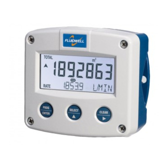
Take careful notice of the " Safety rules, instructions and precautionary measures " in the front of this manual. This chapter describes the daily use of the F012-A. This instruction is meant for users / operators. 2.2. CONTROL PANEL The following keys are available: Fig. -
Page 7: Operator Information And Functions
SETUP-settings. The signal generated by the connected flowmeter is measured by the F012-A in the background, whichever screen refresh rate setting is chosen. After pressing a key, the display will be updated very quickly during a 30 second period, after which it will slow-down again. - Page 8 Page 8 Range error As soon as the input value is 5% outside the calibrated measuring range, “ALARM” will be displayed. Meanwhile, the calibrated value will be displayed. After pressing the SELECT key, the reason of the alarm will be displayed: “LO RANGE” or “HI RANGE”.
-
Page 9: Configuration
Personnel must read and understand this Operating Manual before carrying out its instructions. The F012-A may only be operated by personnel who are authorized and trained by the operator of the facility. All instructions in this manual are to be observed. - Page 10 Page 10 Matrix structure SETUP-level: SCROLLING THROUGH SETUP-LEVEL Selection of function-group and function: SETUP is divided into several function groups and functions. Each function has a unique number, which is displayed below the word "SETUP" at the bottom of the display. The number is a combination of two figures. The first figure indicates the function-group and the second figure the sub-function.
- Page 11 Page 11 To change or select a value: To change a value, use to select the digits and to increase that value. If the new value is invalid, the increase sign or decrease-sign will be displayed while you are programming.
-
Page 12: Overview Functions Setup Level
CUT-OFF 0.0 - 99.9% CALIBRATE LOW default - calibrate - calibrate set CALIBRATE HIGH default - calibrate - calibrate set OTHERS TYPE / MODEL F012-A SOFTWARE VERSION 03.xx.xx SERIAL NO. xxxxxxx PASS CODE 0000 - 9999 TAGNUMBER 0000000 - 9999999... -
Page 13: Explanation Of Setup-Functions
Page 13 3.2.3. EXPLANATION OF SETUP-FUNCTIONS 1 - TOTAL SETUP - 11 determines the measurement unit for total and accumulated MEASUREMENT UNIT total. The following units can be selected: L - m3 - kg - lb. - GAL - USGAL - bbl - _ (no unit). Alteration of the measurement unit will have consequences for operator and SETUP-level values. -
Page 14: Flowrate
Page 14 2 - FLOWRATE The settings for total and flowrate are entirely separate. In this way, different units of measurement can be used for each e.g. cubic meters for total and liters for flowrate. The display update time for flowrate is one second or more. MEASUREMENT UNIT SETUP - 21 determines the measurement unit for flowrate. -
Page 15: Display
When used with the internal battery option, the user can expect reliable measurement over a long period of time. The F012-A has several smart power management functions to extend the battery life time significantly. Two of these functions can be set:... - Page 16 The analog output signal of a flowmeter does mirror the actual flow. This signal is measured several times a second by the F012-A. The value measured is a "snap-shot" of the real flow as it will be fluctuating. With the help of this digital filter a stable and accurate reading can be obtained while the filter level can be set to a desired value.
-
Page 17: Others
TYPE OF MODEL For support and maintenance it is important to have information about the characteristics of the F012-A. Your supplier will ask for this information in the case of a serious breakdown or to assess the suitability of your model for upgrade considerations. -
Page 18: Installation
Personnel must read and understand this Operating Manual before carrying out its instructions. The F012-A may only be operated by personnel who are authorized and trained by the operator of the facility. All instructions in this manual are to be observed. -
Page 19: Dimensions- Enclosure
Page 19 4.3. DIMENSIONS- ENCLOSURE Aluminum enclosures: 75 mm (2.95") 112 mm (4.40") 130 mm (5.12") 12mm 12mm 30mm 30mm 24mm 24mm M20 x 1,5 6 x M12 36mm 36mm 30mm 30mm M16 x 1,5 M16 x 1,5 1/2"NPT M20 x 1,5 0.12"... - Page 20 Page 20 GRP enclosures: 75 mm (2.95") 112 mm (4.40") 130 mm (5.12") HK back box: (flat bottom) 75 mm (2.95") 118 mm (4.65”) 25mm 25mm D=20mm D=20mm 12mm 12mm 30mm 30mm 24mm 24mm D=12mm D=16mm D=16mm D=20mm 36mm 36mm 0.12”...
-
Page 21: Installing The Hardware
This unit must be installed in accordance with the EMC guidelines (Electro Magnetic Compatibility). Do ground the aluminum casing properly as indicated, if the F012-A has been supplied with the 115-230V AC power-supply type PM. The green / yellow wire between the back-casing and removable terminal-block may never be removed. -
Page 22: Terminal Connectors With Power Supply - Type : Pb / Pd / Pl / Px
REMARKS: TERMINAL CONNECTORS: Terminals 1-2; Flowmeter input: The F012-A requires a (0)4-20mA flowmeter signal which will be processed 4 times a second with a 16 bits accuracy. The input is not isolated. The screen of the signal wire must be connected to the common ground terminal... - Page 23 Page 23 Terminal 4-5: POWER SUPPLY UNIT - TYPE PD / PX: To power the unit an internal battery can be used (type PB) and / or an external DC power supply of 8-30V DC (type PX) or 16-30V DC (type PD). Connect the "-"...
-
Page 24: Terminal Connectors With Power Supply - Type : Pf / Pm
TYPE: A PF / PM ANALOG (0)4-20mA Fig. 9: Overview of terminal connectors F012-A-(PF / PM) and options. SENSOR SUPPLY Type PF-PM: Sensor supply: 8.2V, 12V or 24 V: With this option, a real power supply for the sensor is available. The sensor can be powered with 8.2, 12 or 24 V DC (max. - Page 25 400mA@24V DC. Terminals 5-7; Flowmeter input: The F012-A requires a (0)4-20mA flowmeter signal which will be processed 4 times a second with a 16 bit accuracy. The input is not isolated. The screen of the signal wire must be connected to the common ground terminal 5.
-
Page 26: Intrinsically Safe Applications
For installation under FM: this intrinsically safe device must be installed in accordance with the Certificate / Project ID: 3033306. The control drawing number FWCD-0001 can be found in the document named: “Fluidwell F0..-A-XI - Documentation for Intrinsic Safety”. - Page 27 FWCD-0001. Tamb CSA Certificate nr: CSA.08.2059461 – FM Project ID: 3033306 -40°C ... +70°C Made in Veghel, The Netherlands by Fluidwell bv -40°F ... +158°F KEMA 05ATEX1168 X Battery powered applications: II 1 G Ex ia IIC T4 Replace with certified II 1 D Ex iaD 20 IP 65 / 67 T 100°C...
- Page 28 Type PL: the unit will be powered from the 4-20mA input signal. Terminal 4-6 are not available. 5.3. CONFIGURATION EXAMPLES INTRINSICALLY SAFE APPLICATIONS: Configuration example no. 1 Configuration example IIA - IIB and IIC application - F012-A-PX-XI-ZB HAZARDOUS AREA SAFE AREA TERMINAL CONNECTORS F0-series = max.
- Page 29 Page 29 Configuration example no. 2 Configuration example IIA - IIB and IIC application - F012-A-PD-XI-ZB HAZARDOUS AREA SAFE AREA TERMINAL CONNECTORS F0-series = max. 30 V Power supply Supply backlight = max. 200 mA Backlight option: type ZB For example = max.
-
Page 30: Battery Replacement Instructions
Page 30 5.4. BATTERY REPLACEMENT INSTRUCTIONS FW-LiBAT-001 - INST001 Fig. 18: Battery replacement instructions Intrinsically Safe Battery. HF012AEN_v0403_03 Atex_IECEx_CSA_FM... -
Page 31: Maintenance
Personnel must read and understand this Operating Manual before carrying out its instructions. The F012-A may only be operated by personnel who are authorized and trained by the operator of the facility. All instructions in this manual are to be observed. -
Page 32: Appendix A: Technical Specification
Page 32 APPENDIX A: TECHNICAL SPECIFICATION GENERAL Display Type High intensity reflective numeric and alphanumeric LCD, UV-resistant. Digits Seven 17mm (0.67") and eleven 8mm (0.31"). Various symbols and measuring units. Refresh rate User definable: 8 times/sec - 30 secs. Type ZB (option) Bi-color configurable LED-backlight - green or amber. - Page 33 Page 33 Sensor excitation Type PB / PC / PX Sensor supply voltage: 3.2V DC for pulse signals and 1.2V DC for coil pick-up. Please note: this is not a real sensor supply. Only suitable for sensors with a very low power consumption like coils (sine wave) and reed-switches.
- Page 34 Page 34 OPERATIONAL Operator functions Displayed functions total and/or flowrate. total and accumulated total. total can be reset to zero by pressing the CLEAR-key twice. Total Digits 7 digits. Units L, m3, GAL, USGAL, KG, lb, bbl, no unit. Decimals 0 - 1 - 2 or 3.
-
Page 35: Appendix B: Problem Solving
APPENDIX B: PROBLEM SOLVING In this appendix, several problems are included that can occur when the F012-A is going to be installed or while it is in operation. Flowrate displays "0 / zero" while there is flow (total is counting): Check: ... -
Page 36: Index Of This Manual
Page 36 INDEX OF THIS MANUAL accumulated total loop powered actual settings low current backlight low-battery color main-function density maintenance battery life time 15, 31 manual version Battery replacement model clear total operational configuration operator level contents pass code 17, 35 dimensions power supply 23, 25... -
Page 37: List Of Figures In This Manual
Fig. 7: Grounding aluminum enclosure with option PM 115-230V AC..........21 Fig. 8: Overview of terminal connectors F012-A-(PB / PD / PL / PX) and options......22 Fig. 9: Overview of terminal connectors F012-A-(PF / PM) and options........... 24 ... -
Page 38: Notes
Page 38 NOTES HF012AEN_v0403_03 Atex_IECEx_CSA_FM... - Page 39 Page 39 NOTES HF012AEN_v0403_03 Atex_IECEx_CSA_FM...
- Page 40 64 pass code 0000 65 tagnumber 0000000 Fluidwell bv HF012AEN_v0403_03 Atex_IECEx_CSA_FM PO box 6 Voltaweg 23 Website: www.fluidwell.com 5460 AA Veghel 5466 AZ Veghel Find your nearest representative: www.fluidwell.com/representatives The Netherlands The Netherlands Copyright Fluidwell bv - 2012 - HF110AEN_v0501_03...
Need help?
Do you have a question about the F012-A and is the answer not in the manual?
Questions and answers