Table of Contents
Advertisement
Quick Links
Advertisement
Table of Contents

Related Manuals for Fluidwell F090-A-PL


Summary of Contents for Fluidwell F090-A-PL
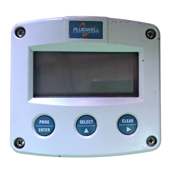
- Page 1 F090-A-PL LOOP POWERED INDICATOR Signal input sensor: 4-20mA. Options: Intrinsically Safe. F-Series - Field mounted indicators for safe and hazardous areas. F-Series - Field mounted indicators for safe and hazardous areas. More info: www.fluidwell.com/fseries More info: www.fluidwell.com/fseries...
-
Page 2: Disposal
▪ This unit must be installed in accordance with the EMC guidelines (Electro Magnetic Compatibility). ▪ Do connect a proper grounding to the aluminum casing as indicated if the F090-A-PL has been supplied with the 115-230V AC power-supply type PM. The green / yellow wire between the back-casing and removable terminal-block may never be removed. -
Page 3: About The Operation Manual
This operation manual describes the standard unit as well as most of the options available. For additional information, please contact your supplier. A hazardous situation may occur if the F090-A-PL is not used for the purpose it was designed for or is used incorrectly. Please carefully note the information in this operating manual indicated by the pictograms: A "warning"... -
Page 4: Table Of Contents
Intrinsically safe applications ...................... 19 Maintenance ..........................23 Appendix A: Technical specification ....................24 Appendix B: Problem solving ......................26 Appendix C: Declaration of Conformity ....................27 Appendix D: Control Drawing ......................28 Index of this manual ..........................29 Notes..............................30 FW-F090-A-PL-M_v0403_07_EN.docx... -
Page 5: Introduction
This manual describes the unit with an analog 4-20mA input type from the sensor "-A version". One sensor with an active 4-20mA signal output can be connected to the F090-A-PL. The F090-A-PL is powered from the loop (sensor signal) and does not require any additional external power supply. - Page 6 All instructions in this manual are to be observed. ▪ Take careful notice of the " Safety rules, instructions and precautionary measures " in the front of this manual. This chapter describes the daily use of the F090-A-PL. This instruction is meant for users / operators. 2.2.
- Page 7 For the Operator, the following functions are available (if activated): ▪ Display value and measuring unit This is the main display information of the F090-A-PL. After selecting any other information, it will always return to this main display automatically. ▪...
-
Page 8: Configuration
Operating Manual before carrying out its instructions. ▪ The F090-A-PL may only be operated by personnel who are authorised and trained by the operator of the facility. All instructions in this manual are to be observed. - Page 9 Additionally, each function is expressed with a keyword. After selecting a sub-function, the next main function is selected by scrolling through all "active" sub- functions (e.g. 1, 11, 12, 13, 14, 1, 2, 3, 31 etc.). FW-F090-A-PL-M_v0403_07_EN.docx...
- Page 10 Note: alterations will only be set after ENTER has been pressed! To return to OPERATOR-level: In order to return to the operator level, PROG will have to be pressed for three seconds. Also, when no keys are pressed for 2 minutes, SETUP will be left automatically. FW-F090-A-PL-M_v0403_07_EN.docx...
- Page 11 Do select “------“ if no time is desired. DECIMALS This setting determines the number of digits following the decimal point. The following can be selected: 000000 - 11111.1 - 222.22 - 33.333 - 4.4444 - .55555 Continued next page >>> FW-F090-A-PL-M_v0403_07_EN.docx...
- Page 12 The bargraph (piegraph) displayed at operator level is percentage-wise related to the input signal: minimum signal is 0% (setup 33) and maximum signal is 100% (setup 34). With this function, the bargraph can be enabled / disabled. Following selections are available: OFF - ON FW-F090-A-PL-M_v0403_07_EN.docx...
- Page 13 The analogue output signal of a sensor does mirror a value. This value is measured several times a second by the F090-A-PL. The value measured is a "snap-shot" of the real signal as it will be fluctuating. With the help of this digital filter a stable and accurate reading can be obtained while the filter level can be set to a desired value.
- Page 14 TYPE OF MODEL For support and maintenance it is important to have information about the characteristics of the F090-A-PL. Your supplier will ask for this information in the case of a serious breakdown or to assess the suitability of your model for upgrade considerations.
-
Page 15: Installation
Operating Manual before carrying out its instructions. ▪ The F090-A-PL may only be operated by personnel who are authorised and trained by the operator of the facility. All instructions in this manual are to be observed. - Page 16 1/2"NPT M20 x 1,5 0.12" 0.12" M20 x 1,5 3x 1/2"NPT 25mm 25mm 15 15 M20 x 1,5 M20 x 1,5 4x M20 x 1,5 29.1 mm (1.15”) 115 mm (4.53”) 31 mm (1.22”) Fig. 4: Dimensions Aluminum enclosures. FW-F090-A-PL-M_v0403_07_EN.docx...
- Page 17 118 mm (4.65”) 25mm 25mm D=20mm D=20mm 12mm 12mm 30mm 30mm 24mm 24mm D=12mm D=16mm D=16mm D=20mm 36mm 36mm 0.12” 0.12” D=22mm (0.866") 3x D=22mm (0.866”) 29.1 mm (1.15”) 115 mm (4.53”) 31 mm (1.22”) Fig. 5: Dimensions GRP enclosures. FW-F090-A-PL-M_v0403_07_EN.docx...
- Page 18 REMARKS: TERMINAL CONNECTORS: Terminals 1-2; sensor INPUT LOOP POWERED 4-20mA - type A-PL: Model F090-A-PL is powered from the 4-20mA sensor signal. The unit will process the signal four times a second with a 16 bits accuracy. The input is not isolated.
-
Page 19: Intrinsically Safe Applications
Safety Instructions ▪ Certificates, safety values, control drawing and declaration of compliance can be found in the document named: “Fluidwell F0..-A-XI - Documentation for Intrinsic Safety”. ▪ For installation under ATEX directive: this intrinsically safe device must be installed in accordance with the Atex directive 94/9/EC and the product certificate KEMA 05ATEX1168 X. - Page 20 Terminal connectors F090-A-PL-XI-(ZB): SENSOR SIGNAL POWER SUPPLY BACKLIGHT ANALOG INPUT OPTION: ZB TYPE: A-PL 4-20mA Fig. 9: Overview terminal connectors XI - Intrinsically Safe applications. Power supply: Type PL: the F090-A-PL-XI will be powered from the 4-20mA input signal. FW-F090-A-PL-M_v0403_07_EN.docx...
- Page 21 Page 21 5.3. CONFIGURATION EXAMPLE INTRINSICALLY SAFE APPLICATION: Configuration example Configuration example IIA - IIB and IIC application - F090-A-PL-XI-ZB HAZARDOUS AREA SAFE AREA TERMINAL CONNECTORS F0-series = max. 30 V Power supply Supply backlight Backlight option: type ZB = max. 200 mA For example = max.
- Page 22 8. If necessary, get access to the setup menu and make any adjustments to obtain the correct settings. 5.4.3. DISPOSAL OF BATTERIES • Batteries pose an environmental hazard. • Do not dispose of as general waste or incinerate. • Return used batteries to a recycling point. FW-F090-A-PL-M_v0403_07_EN.docx...
-
Page 23: Maintenance
Operating Manual before carrying out its instructions. ▪ The F090-A-PL may only be operated by personnel who are authorized and trained by the operator of the facility. All instructions in this manual are to be observed. -
Page 24: Appendix A: Technical Specification
Note I.S. application for intrinsically safe applications, consult the safety values in the certificate. Terminal connections Type: Removable plug-in terminal strip. Wire max. 1.5mm2 Data protection Type EEPROM backup of all setting. Data retention at least 10 years. Pass code Configuration settings can be pass code protected. FW-F090-A-PL-M_v0403_07_EN.docx... - Page 25 - mwc - inwc - ftwc - Ph - mV - no unit. Time unit sec - min - hour - day - no unit Decimals 0 – 1 – 2 – 3 – 4 or 5. Piegraph Digits 10 segments. Relation to the minimum and maximum input signal (0-100%). FW-F090-A-PL-M_v0403_07_EN.docx...
-
Page 26: Appendix B: Problem Solving
Page 26 APPENDIX B: PROBLEM SOLVING In this appendix, several problems are included that can occur when the F090-A-PL is going to be installed or while it is in operation. Display is "0 / zero" while a higher signal is available: Check: ▪... -
Page 27: Appendix C: Declaration Of Conformity
Page 27 APPENDIX C: DECLARATION OF CONFORMITY FW-F090-A-PL-M_v0403_07_EN.docx... -
Page 28: Appendix D: Control Drawing
Page 28 APPENDIX D: CONTROL DRAWING FW-F090-A-PL-M_v0403_07_EN.docx... -
Page 29: Index Of This Manual
..........3 Span ............12 subfunction .............9 time unit ............ 11 tagnumber ........... 14 functional description ........5 technical specification ......... 24 hardware version ........... 3 terminal connectors ........18 input loop powered ........18 version software .......... 14 FW-F090-A-PL-M_v0403_07_EN.docx... -
Page 30: Notes
Page 30 NOTES FW-F090-A-PL-M_v0403_07_EN.docx... - Page 31 Page 31 NOTES FW-F090-A-PL-M_v0403_07_EN.docx...
- Page 32 _ _ _ _ _ _ _ 44 pass code 0000 45 tagnumber 0000000 Fluidwell bv FW-F090-A-PL-M_v0403_07_EN.docx PO box 6 Voltaweg 23 Website: www.fluidwell.com 5460 AA Veghel 5466 AZ Veghel Find your nearest representative: www.fluidwell.com/representatives The Netherlands The Netherlands Copyright Fluidwell bv - © 2019- FW-F090-A-PL-M_v0403_07_EN.docx...
Need help?
Do you have a question about the F090-A-PL and is the answer not in the manual?
Questions and answers