Table of Contents
Advertisement
Quick Links
Advertisement
Table of Contents

Subscribe to Our Youtube Channel
Related Manuals for THORLABS TLS001-635


Summary of Contents for THORLABS TLS001-635
- Page 1 TLS001-635 TLS001-1550 T-Cube Laser Source User Guide Original Instructions...
-
Page 2: Table Of Contents
Contents Chapter 1 Safety .................... 4 1.1 Safety Information .................. 4 1.2 General Warnings .................. 4 1.3 Warnings Relating To Laser Safety ............5 1.4 Laser Markings ..................5 Chapter 2 Overview and Setup ..............6 2.1 Introduction ..................... 6 2.2 T-Cube Controller Hub ................ - Page 3 6.2 Settings Panel ..................30 Appendices Appendix A Preventive Maintenance ............32 Appendix B Specifications and Associated Parts ........33 Appendix C APTLaser Control Method Summary ........34 Appendix D Regulatory ................36 Appendix E Thorlabs Worldwide Contacts ..........39...
-
Page 4: Chapter 1 Safety
Chapter 1 Safety 1.1 Safety Information For the continuing safety of the operators of this equipment, and the protection of the equipment itself, the operator should take note of the Warnings, Cautions and Notes throughout this handbook and, where visible, on the product itself. The following safety symbols may be used throughout the handbook and on the equipment itself. -
Page 5: Warnings Relating To Laser Safety
To prevent injury, all personnel in the vicinity of the laser source should wear appropriate eye protection. 1.4 Laser Markings The TLS001-1550 is a Class 1 laser product. The TLS001-635 is a Class 3R laser product. The units are marked as follows:: TLS001-1550... -
Page 6: Chapter 2 Overview And Setup
Chapter 2 Overview and Setup 2.1 Introduction The TLS001 T-Cube is a Fiber Coupled Laser source for stand alone operation or use with the T-Cube Controller Hub. It uses an internally-pigtailed Fabry-Perot laser diode that is connected to the rear panel FC feedthrough via a single mode fiber. By connecting a fiber to fiber connection at the output, these devices deliver more useful optical power than systems that use a receptacle with embedded optics. -
Page 7: T-Cube Controller Hub
2.2 T-Cube Controller Hub As a further level of convenience when using these controllers, Thorlabs also offers the new K-Cube Controller Hubs (KCH301 and KCH601). This product has been designed specifically with multiple T-Cube operation in mind in order to simplify issues such as cable management, power supply routing, multiple USB device communications and different optical table mounting scenarios. -
Page 8: Apt Pc Software Overview
Chapter 2 2.3 APT PC Software Overview 2.3.1 Introduction As a member of the APT range of controllers, the TLS001 Laser Source shares many of the associated software benefits. This includes USB connectivity (allowing multiple units to be used together on a single PC), fully featured Graphical User Interface (GUI) panels, and extensive software function libraries for custom application development. -
Page 9: Aptuser Utility
T-Cube Laser Source 2.3.2 APTUser Utility The APTUser application allows the user to interact with a number of APT hardware control units connected to the host PC. This program displays multiple graphical instrument panels to allow multiple APT units to be controlled simultaneously. All basic operating parameters can be altered and, similarly, all operations (such as laser intensity adjustment) can be initiated. -
Page 10: Apt Config Utility
Chapter 2 2.3.3 APT Config Utility There are many system parameters and configuration settings associated with the operation of the APT Server. Most can be directly accessed using the various graphical panels, however there are several system wide settings that can only be made 'off-line' before running the APT software. -
Page 11: Apt Server (Activex Controls)
T-Cube Laser Source 2.3.4 APT Server (ActiveX Controls) ActiveX Controls are re-usable compiled software components that supply both a graphical user interface and a programmable interface. Many such Controls are available for Windows applications development, providing a large range of re-usable functionality. -
Page 12: Software Upgrades
APT controllers. 2.3.5 Software Upgrades Thorlabs operate a policy of continuous product development and may issue software upgrades as necessary. Detailed instructions on installing upgrades are included on the APT Software CD ROM. -
Page 13: Chapter 3 Getting Started
If you experience any problems when installing software, contact Thorlabs on +44 (0)1353 654440 and ask for Technical Support. DO NOT CONNECT THE CONTROLLER TO YOUR PC YET 1) Go to Services/Downloads at www.thorlabs.com and download the APT software. -
Page 14: Mechanical Installation
Chapter 3 3.2 Mechanical Installation 3.2.1 Environmental Conditions Warning Operation outside the following environmental limits may adversely affect operator safety. Location Indoor use only Maximum altitude 2000 m Temperature range C to 40 Maximum Humidity Less than 80% RH (non-condensing) at 31°C To ensure reliable operation the unit should not be exposed to corrosive agents or excessive moisture, heat or dust. -
Page 15: Removing The Baseplate
T-Cube Laser Source 3.2.3 Removing the Baseplate The baseplate must be removed before the rubber feet (supplied) can be fitted, or the unit is connected to the USB controller hub.. Detail A Baseplate attachment screws Detail B Baseplate removed and rubber feet fitted Fig. -
Page 16: Electrical Installation
This input can be driven from a 0 to 10V voltage source. The input impedence is 13kΩ. Note Thorlabs supply a variety of SMA to BNC and SMC to BNC adaptor and extension cables. Please see our catalog, or visit www.Thorlabs.com for further details. 3.3.2 Using the Safety Interlock and Key Switch The TLS001 T-Cube Laser Source is a class 1 (1550 nm) / class 3R (635 nm) laser device and therefore is not required to have a safety interlock and/or key switch. -
Page 17: Using The Tch002 Controller Hub
Cube unit and could result in personal injury. 3.3.4 Supply Voltage and Current Requirements The TLS001 is fitted with a 2.1mm DC connector. Thorlabs offers a compact, 5V single way power supply (TPS101) for use with a single laser source cube. -
Page 18: Connecting To A Standalone Power Supply
3) The Version number of the embedded software is displayed for a few seconds. Thorlabs offers a compact, 5V single way power supply (TPS101) for use with a single laser source cube. Alternatively, the USB controller hub (TCH002) provides power and USB comms for up to 6 T-Cubes (see Section 3.3.3.). -
Page 19: Connect The Hardware 1
T-Cube Laser Source 3.4 Connect The Hardware 1) Perform the mechanical installation as detailed in Section 3.2. 2) Connect the connectorized output fiber to the unit - see Section 3.3.1. 3) Connect the laser source unit to the power supply - see Section 3.3.5. 4) Connect the INTERLOCK jack plug - see Section 3.3.2. -
Page 20: Chapter 4 Standalone Operation
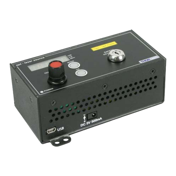
Chapter 4 Standalone Operation 4.1 Introduction The control panel of the TLS001 Laser Source T-Cube contains a 5 digit 7 Segment display, adjustment potentiometer, Mode button and safety keyswitch. The following brief overview explains how the front panel controls can be used to perform a typical series of operations. -
Page 21: Output Potentiometer Operation
Caution The output power of the TLS001-635 can be driven beyond 2.5mW. The displays, both LED and GUI are accurate up to 2.5mW readings, higher outputs are not linear and laser output can be higher than displayed. - Page 22 Chapter 4 Display Settings The display can be set to show the laser output in mW, mA or dBm. If mW is selected, the display shows the laser output power. If mA is selected, the display shows the laser current. If dBm is selected, the display shows the laser output power in dBm.
-
Page 23: Manual Operation Tutorial
T-Cube Laser Source Adjustment Settings The adjustment settings allow the user to select the method of laser power adjustment. is selected, the power is controlled via an external 0 to 10V I/P connected to the EXT IN terminal on the rear panel. is selected, the power is controlled via the OUTPUT potentiometer on the top panel. -
Page 24: Introduction
3) Fit the INTERLOCK jack plug - see Section 3.3.2. 4) Turn the Key Switch ON. 5) Run the APT User program - Start/All Programs/Thorlabs/APT User/APT User. The APT server registers automatically the units connected on the USB bus and... - Page 25 T-Cube Laser Source 6) Click the ‘Enable’ button on the GUI to turn ON the laser output. Notice how the LED in the button is lit to indicate that the laser output is ON.. Fig. 5.1 Gui panel showing jog and ident buttons 7) Click the ‘Ident’...
-
Page 26: Creating A Simulated Configuration Using Apt Config
To create a simulated configuration proceed as follows: 1) Run the APT Config utility - Start/All Programs/Thorlabs/APT/APT Config. 2) Click the 'Simulator Configuration' tab. Fig. 5.2 APT Configuration Utility - Simulator Configuration Tab 3) Enter ‘LAB1’... - Page 27 T-Cube Laser Source 4) In the 'Simulator' field, check the ‘Enable Simulator Mode’ box. The name of the most recently used configuration file is displayed in the 'Current Configuration' window. 5) In the ‘Control Unit’ field, select ‘Laser Source T-Cube (TLS001)’.
- Page 28 Chapter 5 6) Enter a 6 digit serial number. Note Each physical APT hardware unit is factory programmed with a unique 8 digit serial number. In order to simulate a set of ‘real’ hardware the Config utility allows an 8 digit serial number to be associated with each simulated unit.
-
Page 29: Chapter 6 Software Reference
Chapter 6 Software Reference 6.1 GUI Panel The following screen shot shows the graphical user interface (GUI) displayed when accessing the controller using the APTUser utility. Fig. 6.1 TLS001 Laser Source Software GUI Note The serial number of the TLS001 unit associated with the GUI panel, the APT server version number, and the version number (in brackets) of the embedded software running on the unit, are displayed in the top right hand corner. -
Page 30: Settings Panel
Chapter 6 Interlock LED - lit green when the ‘Interlock’ jack plug is fitted, red when open circuit - see Section 3.3.2. Enable Button - turns the output of the laser ON and OFF. Note The laser output cannot be enabled unless the interlock jackplug is fitted and the key switch is turned on. - Page 31 T-Cube Laser Source menu) for further details and to Section 2.3.4. for an overview of the APT ActiveX controls). Fig. 6.1 Laser Source Settings Panel Power Control Source - the source(s) which control the output from the laser unit : If Software Only is selected, the unit responds only to software commands and the output to the laser is that set using the SetPowerSetpoint method, or the ‘OUTPUT’...
-
Page 32: Appendix A Preventive Maintenance
The fascia may be cleaned with a soft cloth, lightly dampened with water or a mild detergent. The fibre tip at the Laser Aperture may be cleaned using Thorlabs product FBC1 - One-Step Fiber Bulkhead and Connector Cleaner. -
Page 33: Appendix B Specifications And Associated Parts
1550nm: 1.5mW 635nm: 4.0mW Caution The output power of the TLS001-635 can be driven beyond 2.5mW. The displays, both LED and GUI are accurate up to 2.5mW readings, higher outputs are not linear and laser output can be higher than displayed. -
Page 34: Appendix C Aptlaser Control Method Summary
Appendix C APTLaser Control Method Summary The ActiveX functionality for the TLS001 Laser Source T-Cube is accessed via the APTLaser Control Object, and provides the functionality required for a client application to control a number of T-Cube Laser units. Every hardware unit is factory programmed with a unique 8-digit serial number. This serial number is key to operation of the APT Server software and is used by the Server to enumerate and communicate independently with multiple hardware units connected on the same USB bus. - Page 35 T-Cube Laser Source GetWavelength Gets the output wavelength of the laser source associated with the ActiveX control instance. Identify Identifies the controller by flashing unit LEDs. LLGetStatusBits Gets the controller status bits encoded in 32 bit integer. LLSetGetDigOPs Sets or Gets the user digital output bits encoded in 32 bit integer.
-
Page 36: Appendix D Regulatory
Appendix D Regulatory D.1 Declarations Of Conformity D.1.1 For Customers in Europe This equipment has been tested and found to comply with the EC Directives 89/336/EEC ‘EMC Directive’ and 73/23/EEC ‘Low Voltage Directive’ as amended by 93/68/EEC. Compliance was demonstrated by conformance to the following specifications which have been listed in the Official Journal of the European Communities: Safety EN61010: 2001 Installation Category II, Polution Degree II. - Page 37 OEM laser driver cards) • components • mechanics and optics • left over parts of units disassembled by the user (PCB's, housings etc.). If you wish to return a unit for waste recovery, please contact Thorlabs or your nearest dealer for further information.
- Page 38 Chapter 6 HA0164T Rev F Feb 2018...
-
Page 39: Appendix E Thorlabs Worldwide Contacts
UK and Ireland Thorlabs, Inc. Thorlabs Ltd. sales@thorlabs.com sales.uk@thorlabs.com techsupport@thorlabs.com techsupport.uk@thorlabs.com Europe Scandinavia Thorlabs GmbH Thorlabs Sweden AB europe@thorlabs.com scandinavia@thorlabs.com France Brazil Thorlabs SAS Thorlabs Vendas de Fotônicos Ltda. sales.fr@thorlabs.com brasil@thorlabs.com Japan China Thorlabs Japan, Inc. Thorlabs China sales@thorlabs.jp chinasales@thorlabs.com... - Page 40 Thorlabs Inc. Thorlabs Ltd. 56 Sparta Avenue Saint Thomas Place, Ely Newton, NJ07860 Cambridgeshire CB7 4EX, Tel: +1 973 300 3000 Tel: +44 (0) 1353 654440 Fax: +1 973 300 3600 Fax: +44 (0) 1353 654444 www.thorlabs.com www.thorlabs.com...
Need help?
Do you have a question about the TLS001-635 and is the answer not in the manual?
Questions and answers