Table of Contents
Advertisement
Quick Links
Advertisement
Table of Contents

Subscribe to Our Youtube Channel
Related Manuals for THORLABS TSG001


Summary of Contents for THORLABS TSG001
- Page 1 TSG001 Strain Gauge Reader User Guide Original Instructions...
-
Page 2: Table Of Contents
Contents Chapter 1 Safety ....................4 1.1 Safety Information ...................4 1.2 General Warnings ...................4 Chapter 2 Overview and Setup ..............5 2.1 Introduction ....................2.2 T-Cube Controller Hub ................6 2.3 Kinesis Software Overview ..............7 2.3.1 Introduction ......................7 2.3.2 Kinesis Server ....................7 2.3.3 Software Upgrades .................... - Page 3 Appendix A Connector Pinout Details ............39 Appendix A Preventive Maintenance ............41 Appendix B Specifications and Associated Parts ........42 Appendix C Piezo Operation - Background ..........43 Appendix D Regulatory ................46 Appendix E Thorlabs Worldwide Contacts ..........51...
-
Page 4: Chapter 1 Safety
Chapter 1 Safety 1.1 Safety Information For the continuing safety of the operators of this equipment, and the protection of the equipment itself, the operator should take note of the Warnings, Cautions and Notes throughout this handbook and, where visible, on the product itself. The following safety symbols may be used throughout the handbook and on the equipment itself. -
Page 5: Chapter 2 Overview And Setup
Chapter 2 Overview and Setup 2.1 Introduction The T-Cube Strain Gauge Reader (TSG001) is a new very compact single channel reader, providing immediate 'out of the box' operation. For non-PC use the unit is equipped with an LED Position readout and a mode button to change the display units and set the zero position point. -
Page 6: T-Cube Controller Hub
2.2 T-Cube Controller Hub As a further level of convenience when using the new T-Cube Controllers, Thorlabs also offers the new T-Cube Controller Hub (TCH002). This product has been designed specifically with multiple T-Cube operation in mind in order to simplify issues such as cable management, power supply routing, multiple USB device communications and different optical table mounting scenarios. -
Page 7: Kinesis Software Overview
T-Cube Strain Gauge Reader 2.3 Kinesis Software Overview 2.3.1 Introduction The T-Cube range of controllers share many of the benefits. These include USB connectivity (allowing multiple units to be used together on a single PC), fully featured Graphical User Interface (GUI) panels, and extensive software function libraries for custom application development. - Page 8 Chapter 2 Consider the control supplied for a TSG001 Strain Gauge T-Cube unit. This Control provides a complete user graphical instrument panel to allow the Strain Gauge unit to be manually operated, as well as a complete set of software functions (often called methods) to allow all parameters to be set and Strain Gauge control operations to be automated by a client application.
-
Page 9: Software Upgrades
This is available either by pressing the F1 key when running the Kinesis server, or via the Start menu, Start\Programs\Thorlabs\Kinesis\Kinesis Help. 2.3.3 Software Upgrades Thorlabs operate a policy of continuous product development and may issue software upgrades as necessary. The latest software can be downloaded from the ‘services’ section of www.thorlabs.com. -
Page 10: Chapter 3 Getting Started
If you experience any problems when installing software, contact Thorlabs on +44 (0)1353 654440 and ask for Technical Support. DO NOT CONNECT THE CONTROLLER TO YOUR PC YET 1) Go to Services/Downloads at www.thorlabs.com and download the software. -
Page 11: Mechanical Installation
T-Cube Strain Gauge Reader 3.2 Mechanical Installation 3.2.1 Environmental Conditions Warning Operation outside the following environmental limits may adversely affect operator safety. Location Indoor use only Maximum altitude 2000 m Temperature range C to 40 Maximum Humidity Less than 80% RH (non-condensing) at 31°C To ensure reliable operation the unit should not be exposed to corrosive agents or excessive moisture, heat or dust. -
Page 12: Removing The Baseplate
Chapter 3 3.2.3 Removing the Baseplate The baseplate must be removed before the rubber feet (supplied) can be fitted, or the unit is connected to the USB controller hub.. Detail A Detail B Baseplate attachment screws Baseplate removed and rubber feet fitted Fig. -
Page 13: Electrical Installation
- see Section A.1. for pin out details. Thorlabs supply cabling to connect from this D-type connector to the full range of strain gauge equipped piezo actuators and force sensors. -
Page 14: Strain Gauge - General Information
Chapter 3 3.3.3 Strain Gauge - General Information The typically, the TSG001 is used with strain gauges in a full bridge configuration (Wheatstone). The resistance of each arm of the bridge should be around 350 Ω, since there is a trade-off between resolution and heating of the gauges through too much current. -
Page 15: Supply Voltage And Current Requirements
Section 3.3.4. Connection to a supply of a different rating may cause damage to the unit and could result in injury to the operator. Thorlabs offers a compact, multi-way power supply unit (TPS002), allowing up to two strain gauge driver T-Cubes to be powered from a single mains outlet. -
Page 16: Connect The Hardware 1
Chapter 3 3) The Version number of the embedded software is displayed for a few seconds. Caution If an external power supply is used, ensure that the 3 supply voltages are turned on and off simultaneously. Applying the supply voltages with a large (more than 1 second) time delay between them can result in the strain gauge cube showing an incorrect reading during subsequent operation. -
Page 17: Verifying Software Operation
T-Cube Strain Gauge Reader 3.5 Verifying Software Operation The Software should be installed (Section 3.1.) and the hardware connected (Section 3.4.) before software operation can be verified. Caution In applications requiring the highest level of accuracy and repeatability, it is recommended that the controller unit is powered up approximately 30 minutes before use, in order to allow the internal temperature to stabilize. -
Page 18: Chapter 4 Standalone Operation
The Strain Gauge Reader T-Cube has been designed specifically to operate with the extensive range of Thorlabs piezo-actuated feedback equipped opto-mechanical products. It is also compatible with Thorlabs force sensor products, FSC101 and FSC102 providing high-sensitivity force and touch probe sensing. -
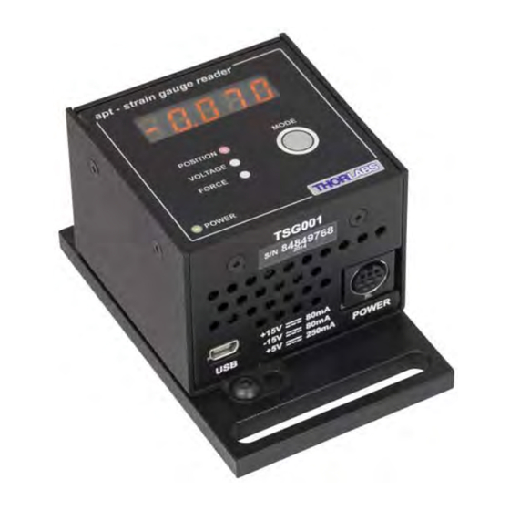
Page 19: Control Panel Buttons And Indicators
T-Cube Strain Gauge Reader 4.2 Control Panel Buttons and Indicators apt - strain gauge reader MODE POSITION VOLTAGE FORCE POWER Fig. 4.1 Panel Controls and Indicators Mode Button 1) Press and release to switch between display modes: POSITION - This mode displays the position of the sensor in µm. VOLTAGE - This mode displays a voltage proportional to the signal measured by the strain gauge, range 0 to 10V (10V is full scale deflection). -
Page 20: Chapter 5 Operation - Tutorial
1) Power up the hardware, and wait until the TPZ001 has finished booting up, then run the Kinesis software - Start/All Programs/Thorlabs/Kinesis/Kinesis. Note For maximum accuracy, wait approximately 30 mins for the unit to thermally... - Page 21 T-Cube Strain Gauge Reader The server registers automatically the units connected on the USB bus and displays the associated GUI panels as shown below. Fig. 5.1 Typical Software Screen Showing Piezo and Strain Gauge T-Cube GUI 2) The GUI panel for the Strain Gauge Reader T-Cube is displayed - see Fig. 5.2. Fig.
-
Page 22: Introduction To Open And Closed Loop Operation
Closed loop operation is only possible if an external position signal is available to control the piezo cube. For the Thorlabs range of piezo actuators, the TSG001 strain gauge reader is a fully self contained unit that is designed to work with the TPZ001 in closed loop mode, providing the feedback signal necessary for closed loop operation. -
Page 23: Closed Loop Operation
The following procedure describes a typical set up, when a TPZ001 piezo driver cube and a TSG001 Strain Gauge Reader are used on the TCH002 controller hub to drive a piezo actuated stage - see Fig. 5.4 for a general system schematic diagram. - Page 24 Wait while Windows installs the drivers for the new hardware. 9) Run the Kinesis software - Start/All Programs/Thorlabs/Kinesis/Kinesis. 10) Click the ‘Settings’ button on GUI of the Piezo Driver to display the Settings panel (shown below).
- Page 25 T-Cube Strain Gauge Reader Note To identify the piezo unit associated with the GUI panel, click the ‘Ident’ button; the Power LED and the Display of the asssociated controller flashes for a short period. Fig. 5.5 Piezo Driver Settings 11) Make the following parameter settings, as shown in Fig. 5.5 Control Tab Loop Mode - Select Closed Loop Maximum Voltage - Set the corresponding voltage for the piezo being...
- Page 26 Chapter 5 14) Click the ‘Settings’ button on GUI of the Strain Gauge Reader fitted in bay 2, to display the Settings panel (shown below). Note To identify the strain gauge unit associated with a GUI panel, click the ‘Ident’ button; the Power LED on the panel of the asssociated controller flashes for a short period Fig.
-
Page 27: Ub Mounting Options
T-Cube Strain Gauge Reader 5.4.2 Hub Mounting Options When the T-Cube strain gauge reader is used on the hub, together with the TPZ001 piezo driver unit, signals can be routed via dedicated internal communication channels. These channels are selected via the settings panel for each controller. If Channel 1 is selected, the feedback signal runs through all the bays - see Fig. -
Page 28: Electrical Connections And Software Settings - Off Hub Operation
Operation The following procedure describes a typical set up, when a TPZ001 piezo driver cube and a TSG001 Strain Gauge Reader are used to control a piezo actuated stage - see Fig. 5.8 for a general system schematic diagram.. Fig. 5.8 Typical System Set Up - Off Hub (Hard Wired) Operation 1) Perform the mechanical installation as detailed in Section 3.2. - Page 29 T-Cube Strain Gauge Reader 10) Click the ‘Settings’ button on the GUI panel of the Piezo Driver to display the Settings panel (shown below). . Fig. 5.9 Piezo Driver Settings 11) Make the following parameter settings, as shown in Fig. 5.5 Control Tab Loop Mode - Select Closed Loop Maximum Voltage - Set the corresponding voltage for the piezo being...
-
Page 30: Setting The Position Sensor Zero
Chapter 5 5.5 Setting the Position Sensor Zero The strain gauge or force sensor connected to the T-Cube may give a small signal when the device is at zero position with zero volts applied (due to limitations in manufacture, or temperature fluctuations). This 'offset' signal must be removed before the position attained by a specific applied voltage and the position attained by a corresponding specified distance can be rationalized. -
Page 31: Using The Strain Gauge Reader T-Cube With A Piezo Driver T-Cube
Note The piezo position can be adjusted only when a Strain Gauge T-Cube (TSG001) is connected and when operating in ‘Closed Loop’ mode. The position of the actuator is relative to the minimum position set for the arrangement using the ‘Null’ facility, see Section 5.5. The extension of the actuator is displayed on the Strain Gauge T-Cube as a position in microns. -
Page 32: Using The Controller With A Force Sensor
Chapter 5 5.7 Using the Controller with a Force Sensor The Strain Gauge Reader unit can also be used to control a force sensor. 1) In the GUI panel, click the ‘Settings’ button to display the settings panel. 2) In the Display Mode field, select ‘Force’. 3) In the ‘Force Calibration Settings field, enter the calibration factor for the type of force sensor being used. -
Page 33: Setting Move Sequences
T-Cube Strain Gauge Reader The force sensor may display an offset when no contact is apparent. This latent offset must be removed, such that the sensor only detects a force when contact is experienced. To remove the offset proceed as follows. 5) Ensure that the force sensor is correctly orientated in the axis it is to be used. -
Page 34: Chapter 6 Software Reference
Kinesis Software. Fig. 6.1 TSG001 Strain Gauge Reader Software GUI Note The serial number of the TSG001 unit associated with the GUI panel is displayed in the top right hand corner. This information should always be provided when requesting customer support. -
Page 35: Settings Panel
T-Cube Strain Gauge Reader Active - lit when the unit is operating normally and no error condition exists. Error - lit when a fault condition occurs, e.g. the strain gauge unit is powered up without a feedback input connected. Identify - when this button is pressed, the POWER LED and the main display on the front panel of the associated hardware unit will flash for a short period. -
Page 36: Settings Tab
T-Cube Piezo Driver unit (TPZ001) on the T-Cube Controller Hub (TCH002), high precision closed loop operation is possible using the complete range of feedback equipped piezo actuators available from Thorlabs. If Channel 1 is selected, the feedback signal runs through all the bays - see Fig. - Page 37 T-Cube Strain Gauge Reader bay options, and their associated Analogue Input Source (EXT IN) settings are described in Fig. 6.3 on the next page. Caution In general, when members of the T-Cube family are on the TCH002 controller hub, using the signal channels (Channel 1 and Channel 2), users must ensure that: The individual cubes are set up to use the intended signal channel.
- Page 38 Chapter 6 all units set to Hub Channel 2 bay 1 bay 2 bay 3 bay 4 MODE MODE POSITION POSITION VOLTAGE VOLTAGE FORCE FORCE POWER POWER Hub Channel 1 Hub Channel 2 bay 2 bay 3 bay 5 bay 6 MODE MODE POSITION...
-
Page 39: Appendix A Connector Pinout Details
† Power supply for the piezo actuator feedback circuit. It must not be used to drive any other circuits or devices. * This signal is applicable to Thorlabs piezo actuators fitted with an ID resistor. It enables the system to identify the piezo extension associated with the actuator. - Page 40 A.2.1 Pin Identification Thorlabs recommends that the Strain Gauge Reader T-Cube is operated with Thorlabs power supply TPS002, as it was specifically designed for use with this product. However, to enable customers to use the cube in installations where a ±15V and 5V power is already available, the unit can be operated with a different external power supply, such as a bench or lab supply.
-
Page 41: Appendix A Preventive Maintenance
The equipment contains no user servicable parts. There is a risk of severe electrical shock if the equipment is operated with the covers removed. Only personnel authorized by Thorlabs Ltd and trained in the maintenance of this equipment should remove its covers or attempt any repairs or adjustments. -
Page 42: Appendix B Specifications And Associated Parts
Part Number Drive Cable for Piezoelectric Actuators (3.0 m) PAA100 Drive Cable for Piezoelectric Actuators (1.5 m) PAA101 T-Cube Strain Gauge Reader TSG001 Piezoelectric Feedback Cable, Male D-type to Female LEMO PAA622 converter (3.0 m) 2-Way Power Supply Unit TPS002... -
Page 43: Appendix C Piezo Operation - Background
– see Fig. D.1. In this way, the distance from positive to negative electrodes is very small. A large field gradient can therefore be obtained with a modest drive voltage (75 V in the case of Thorlabs actuators). expansion piezoelectric... - Page 44 Some Thorlabs nanopositioning actuators have position sensing, others do not. The Piezoelectric control module allows both types to be controlled.
- Page 45 T-Cube Strain Gauge Reader moving open loop control part demand actuator moving closed loop control part demand a + b/s actuator sensor Fig. D.3 Open loop and closed loop control The result of using closed-loop control is a linear relationship between demand (voltage) and measured position –...
-
Page 46: Appendix D Regulatory
Appendix E Regulatory E.1 Declarations Of Conformity See Section E.3. E.1.1 For Customers In The USA This equipment has been tested and found to comply with the limits for a Class A digital device, persuant to part 15 of the FCC rules. These limits are designed to provide reasonable protection against harmful interference when the equipment is operated in a commercial environment. - Page 47 • left over parts of units disassembled by the user (PCB's, housings etc.). If you wish to return a unit for waste recovery, please contact Thorlabs or your nearest dealer for further information. E.2.2 Waste treatment on your own responsibility If you do not return an "end of life"...
- Page 48 Appendix E E.3 CE Certificate HA0144T Rev 10K Sept 2015...
- Page 49 T-Cube Strain Gauge Reader...
- Page 50 Appendix E HA0144T Rev 10K Sept 2015...
-
Page 51: Appendix E Thorlabs Worldwide Contacts
UK and Ireland Thorlabs, Inc. Thorlabs Ltd. sales@thorlabs.com sales.uk@thorlabs.com techsupport@thorlabs.com techsupport.uk@thorlabs.com Europe Scandinavia Thorlabs GmbH Thorlabs Sweden AB europe@thorlabs.com scandinavia@thorlabs.com France Brazil Thorlabs SAS Thorlabs Vendas de Fotônicos Ltda. sales.fr@thorlabs.com brasil@thorlabs.com Japan China Thorlabs Japan, Inc. Thorlabs China sales@thorlabs.jp chinasales@thorlabs.com... - Page 52 www.thorlabs.com...
Need help?
Do you have a question about the TSG001 and is the answer not in the manual?
Questions and answers